Survey system

a surveillance system and remote control technology, applied in the field of surveillance systems, can solve the problems of increased consumption power and uneven surveillance, and achieve the effects of reducing the time required for automatic collimation, and extending the rang

Active Publication Date: 2007-03-20
KK TOPCON
View PDF7 Cites 43 Cited by
  • Summary
  • Abstract
  • Description
  • Claims
  • Application Information

AI Technical Summary

Benefits of technology

[0009]The present invention was developed in view of the above-described problems and addresses the above-described problems. It is therefore an object of the invention to provide a survey system capable of transmitting guide light to a sufficient distance in a wide range with small power in a survey system, in which guide light is emitted from a target side and is received by the survey apparatus side, capable of shortening the time required for automatic collimation by knowing a rough direction of the target.

Problems solved by technology

However, if a survey is carried out by using a survey apparatus provided with such an automatic collimation device on the basis of an instruction from the remote controller, since it is necessary to cause the telescope to scan a wide range in order to grasp a target in the visual field of the telescope, automatic collimation takes much time, wherein there is a problem in that the survey is not smoothly carried out.
Therefore, it is necessary that signal light from the remote controller 27 is irradiated across a wide range, wherein there occurs a problem in that consumption power is increased, and there is another problem in that a range which can be surveyed with a one-man operation is made narrow since the arrival distance of the signal light is shortened if the consumption power is limited.

Method used


Image

  • Survey system
  • Survey system
  • Survey system

Examples


first embodiment

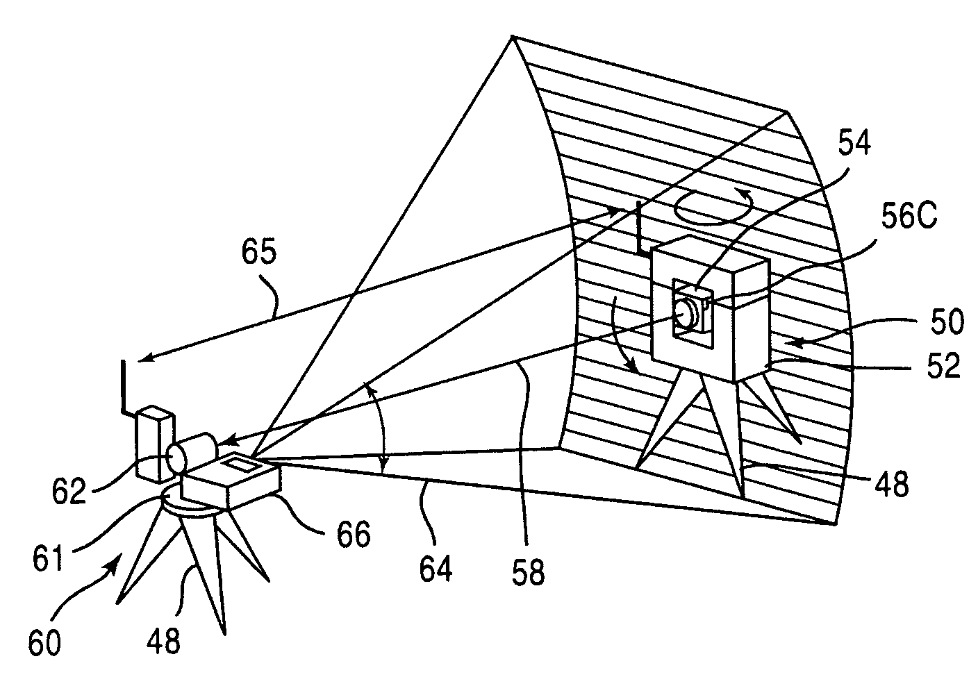
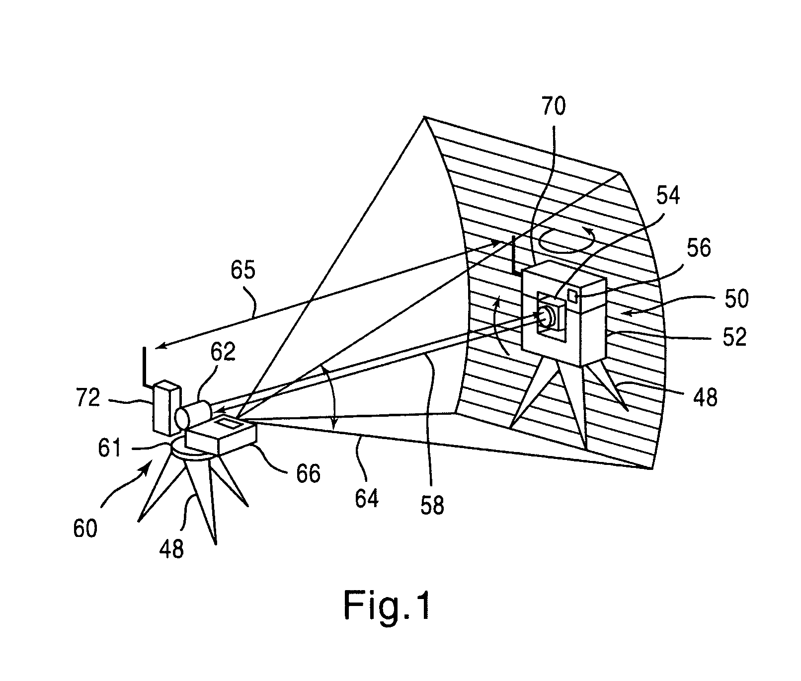
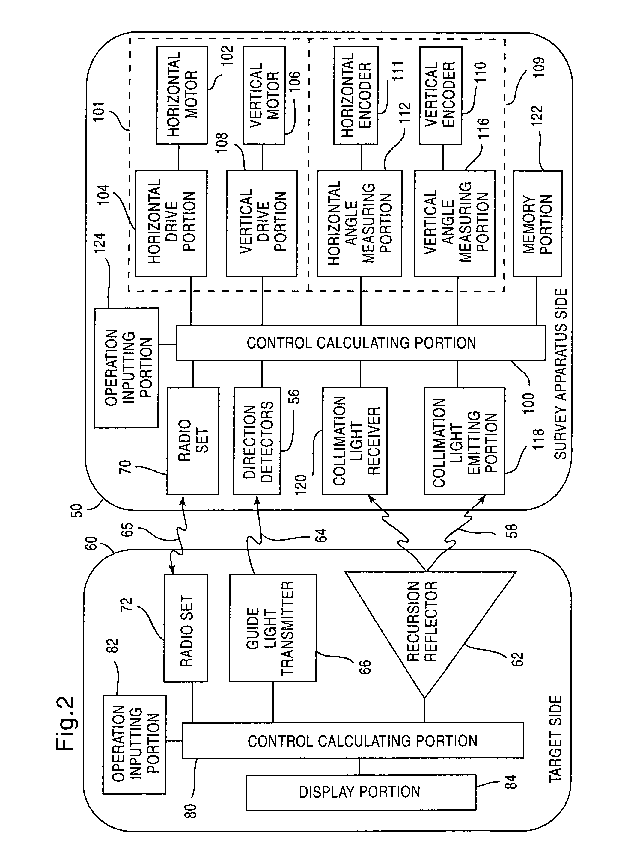
[0045]As shown in FIG. 1, a survey system the invention comprises a survey apparatus 50 provided with an automatic collimation device and a target 60 provided with a recursion reflector 62, such as a reflection prism, which reflects light in its incoming direction. The survey apparatus 50 is provided with a survey apparatus body 52, which can horizontally turn, on a leveling-up table 61 fixed on a tripod 48, and a telescope 54, which can vertically turn, on the survey apparatus body 52. The target 60 is provided, on the leveling-up table 61 fixed on the tripod 48, with a recursion reflector 62 for reflecting collimation light emitted from the survey apparatus 50 toward the survey apparatus 50 and a guide light transmitter 66 for emitting guide light 64, which informs the direction of the recursion reflector 62, toward the survey apparatus 50. The above-described collimation light includes modulation light.

[0046]The guide light 64 is scanned in the vertical direction with a fan beam ...

second embodiment

[0067]Next, the present invention will be described below with reference to FIG. 4 through FIGS. 6A and 6B. FIG. 4 is a view showing the outline of a survey system according to the present embodiment. FIG. 5 is a block diagram showing the survey system. FIGS. 6A and 6B are a flow chart describing movements of the survey system.

[0068]As shown in FIG. 4 and FIG. 5, the survey system according to the present embodiment differs from the above-described first embodiment in that a collimation light receiver 90 for detecting the vertical direction is provided at the target 60 side. The second embodiment is the same as the first embodiment excepting this point. Therefore, in FIG. 4 and FIG. 5, parts which are the same as those described with respect to the first embodiment are referred to by the same reference numbers. A detailed description of the parts which are the same will not be repeated here. In addition, the steps shown in the flow chart of FIGS. 6A and 6B are the same as those in t...

third embodiment

[0073]Further, a description of the present invention will now be provided with reference to FIG. 7 through FIG. 9. FIG. 7 is a view showing the outline of a survey system according to the present embodiment. FIG. 8 is a block diagram showing the survey system. FIG. 9 is a flow chart describing movements of the survey system.

[0074]As shown in FIG. 7 and FIG. 8, in the survey system according to the present embodiment, the survey apparatus 50 and target 60 are not provided with any radio. A horizontal direction detector 55 for detecting the horizontal direction of the telescope 54 is connected to the control calculating portion 100. The horizontal direction detector 55 comprises a horizontal direction detector 56a, which is able to horizontally turn on the survey apparatus body 52, for receiving guide light 64 from the target 60, an encoder 57a for the horizontal direction detector, which detects the turning angle of the horizontal direction detector 56a and a horizontal angle measur...


PUM


Abstract

A survey system for transmitting guide light for instructing the direction of a target, the guide light having a wide range with small power. The survey system includes a target having a recursion reflector for reflecting light and a survey apparatus having an automatic collimation device for automatically coinciding the collimation axis of the recursion reflector with that of a telescope. The target includes a guide light transmitter for emitting guide light and scans a fan beam that is wide in the horizontal direction and narrow in the vertical direction in the vertical direction as guide light. The survey apparatus includes a direction detector for receiving guide light and detecting the direction of the guide light transmitter and also includes a collimation preparing device for turning the telescope roughly to the recursion reflector based on an output signal from the direction detector prior to commencing the automatic collimation.

Description

FIELD OF THE INVENTION[0001]The present invention relates to a survey system capable of remotely controlling a survey apparatus from a target side.BACKGROUND OF THE INVENTION[0002]In order to measure the position, etc., of a measuring point by a survey apparatus such as a conventional total station (electronic type distance and angle measuring apparatus), it was necessary to collimate a target installed at the measuring point. Recently, in order to relieve labor for collimating a target and decrease errors in collimation due to the peculiarities of an operator, a survey apparatus has been released, which is provided with an automatic collimation device. The automatic collimation device automatically turns a telescope toward the direction of a target by emitting collimation light along the optical axis of the telescope of a survey apparatus, receiving the collimation light reflected by the target, and thus obtaining the direction of the target. The above-described collimation light i...

Claims


Application Information

Patent Timeline
Patent Type & Authority Patents(United States)
IPC IPC(8): G01B11/26G01C1/00G01C15/00G01C1/02G01C3/00G01C3/02G01C15/06G01S17/42G02B7/04H01J3/14
CPCG01C15/002G01S17/42G01S7/481G01C1/02G01C3/02G01C15/00G01C15/06
Inventor SUGIURA, AKINOBU
Owner KK TOPCON
Why Eureka
Try Eureka