Reduction of speckle and interference patterns for laser projectors

a laser projector and interference pattern technology, applied in the field of coherently illuminated systems, can solve the problems of laser speckle, random spatial interference of coherent laser light with itself, constructive and destructive interference, etc., and achieve the effect of reducing laser speckle and interference patterns

Inactive Publication Date: 2007-03-20
EVANS & SUTHERLAND COMP
View PDF4 Cites 36 Cited by
  • Summary
  • Abstract
  • Description
  • Claims
  • Application Information

AI Technical Summary

Benefits of technology

[0007]The invention provides a system and method for reducing laser speckle and interference patterns in a laser projector display when using a laser projector having a spatial light modulator (SLM) with a defined pixel rate. The method can include the operation of polarizing a laser output of a continuous wave laser such that the laser output is s-polarized with respect to a beam combiner. The s-polarized laser output can be divided into a first laser beam and a second laser beam. A phase of the second laser beam can be modulated with an amplitude sufficient to create a phase delay of approximately half a wavelength of the laser output and at a frequency at least twice that of the SLM's pixel rate.

Problems solved by technology

Laser speckle can be caused by interference patterns generated when coherent light illuminates a rough surface.
When the laser beam from the projector hits the display screen, the light reflects off the surface at various angles and random spatial interference of the coherent laser light with itself occurs.
The resulting interference of the coherent light source causes constructive and destructive interference.
Whereas speckle is caused by interference of the light scattered from the screen, the diffractive elements in the path of a laser beam can cause an interference pattern in the light incident on the screen.
However, this method is only effective for lasers that have a short coherence length.
An instrument can become difficult to package as the coherence length increases.
However, use of the phase gratings can result in a loss of light when the laser beam is diffracted into higher order diffraction orders with angles that can be too great to be collected by the optics.
Further, while the phase grating can reduce speckle contrast, use of phase gratings can also create objectionable interference patterns on the screen.
Use of the phase gratings can merely result in trading one image artifact for another.
However, the method does not reduce the objectionable interference patterns that can appear in the image incident on the screen due to the diffractive elements in the projector.
Further, while this method could be used with the static phase grating above, it provides no additional improvement when used with the vibrating phase grating above, since both methods must change with each scan of the projector.

Method used


Image

  • Reduction of speckle and interference patterns for laser projectors
  • Reduction of speckle and interference patterns for laser projectors
  • Reduction of speckle and interference patterns for laser projectors

Examples


Embodiment Construction

[0011]Reference will now be made to the exemplary embodiments illustrated in the drawings, and specific language will be used herein to describe the same. It will nevertheless be understood that no limitation of the scope of the invention is thereby intended. Alterations and further modifications of the inventive features illustrated herein, and additional applications of the principles of the inventions as illustrated herein, which would occur to one skilled in the relevant art and having possession of this disclosure, are to be considered within the scope of the invention.

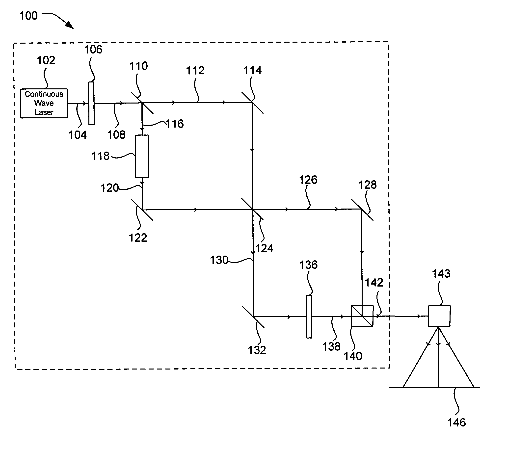
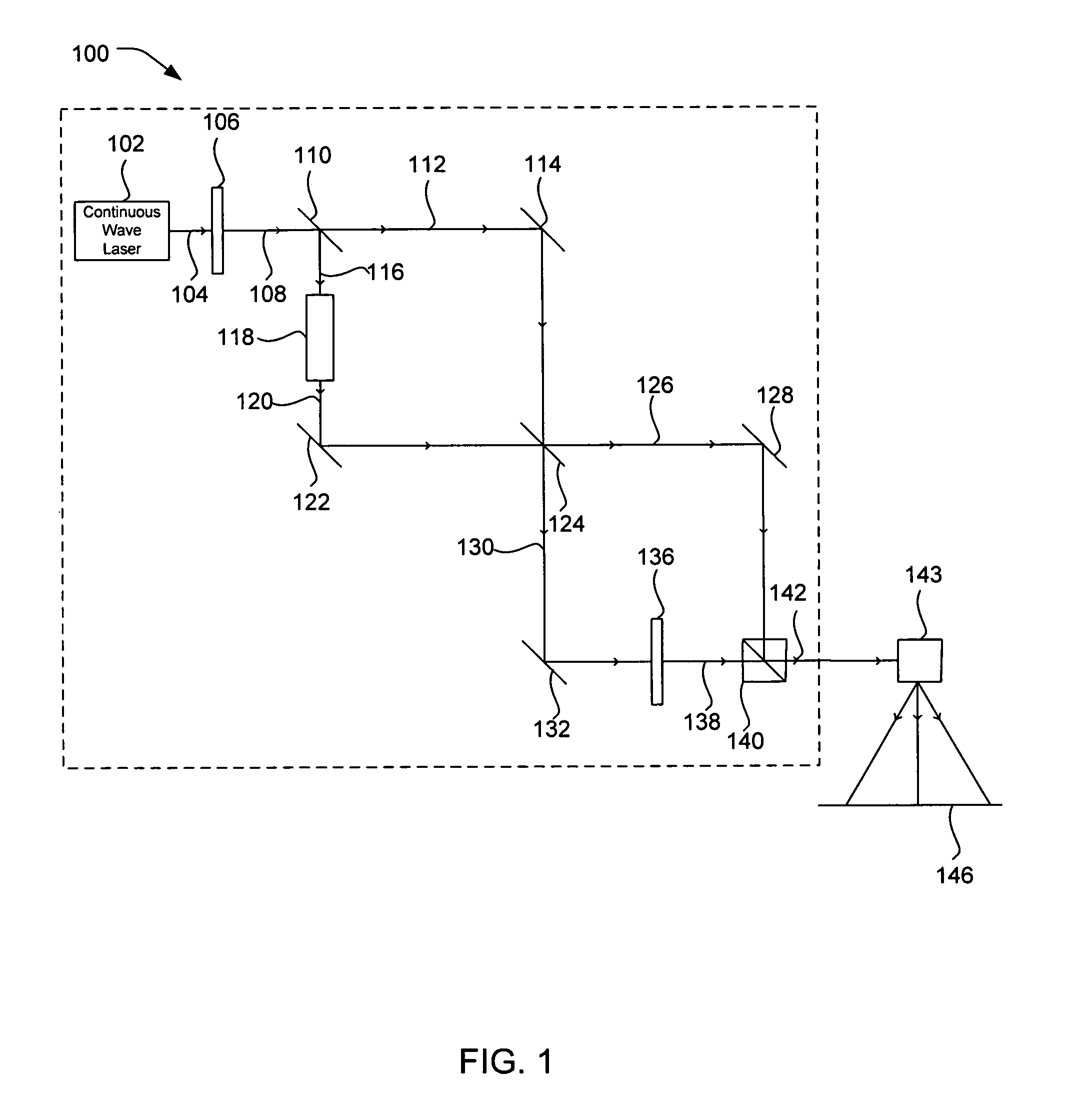
[0012]In order to overcome the problems described and to provide an efficient system for reducing visual obscurities in a laser projector display, the present invention provides an apparatus and method for reducing laser speckle and interference patterns in a laser projector display when using a laser projector having a spatial light modulator (SLM) with a defined pixel rate as illustrated in FIG. 1. The defined ...


PUM

PropertyMeasurementUnit
oscillation frequencyaaaaaaaaaa
frequencyaaaaaaaaaa
integration timeaaaaaaaaaa

Abstract

The invention provides a system and method for reducing laser speckle and interference patterns in a laser projector display when using a laser projector having a spatial light modulator (SLM) with a defined pixel rate. The method can include the operation of polarizing a laser output of a continuous wave laser such that the laser output is s-polarized with respect to a beam combiner. The s-polarized laser output can be divided into a first laser beam and a second laser beam. A phase of the second laser beam can be modulated with an amplitude sufficient to create a phase delay of approximately half a wavelength of the laser output and at a frequency at least twice that of the SLM's pixel rate.

Description

FIELD OF THE INVENTION[0001]The present invention relates generally to the field of coherently illuminated systems. More particularly, the present invention relates to the reduction of speckle and interference patterns in laser illuminated projection systems.BACKGROUND OF THE INVENTION[0002]Laser speckle can be caused by interference patterns generated when coherent light illuminates a rough surface. Reflection from the rough surface can create a diffuse reflection. Transmission through the rough surface creates a diffuse transmission. When light hits a rough surface diffuse reflection and / or diffuse transmission occurs and light scatters in various directions. A laser projector uses a coherent laser beam as its light source. When the laser beam from the projector hits the display screen, the light reflects off the surface at various angles and random spatial interference of the coherent laser light with itself occurs. The resulting interference of the coherent light source causes c...

Claims


Application Information

Patent Timeline
Patent Type & Authority Patents(United States)
IPC IPC(8): G02F1/01
CPCH04N9/3129G02B27/48G02F1/01H04N5/7416
Inventor CHRISTENSEN, ROBERT R.WILLIAMS, FORREST L.TANNER, ALLEN H.
Owner EVANS & SUTHERLAND COMP
Why Eureka
Try Eureka