Active failsafe detection for differential receiver circuits

a failsafe detection and differential receiver technology, applied in the field of integrated circuits, can solve problems such as uncertainty in the state of the receiver output and havoc in the digital system

Inactive Publication Date: 2005-07-05
TEXAS INSTR INC
View PDF5 Cites 5 Cited by
  • Summary
  • Abstract
  • Description
  • Claims
  • Application Information

AI Technical Summary

Benefits of technology

[0008]The present invention achieves technical advantages as a method, system and apparatus for providing failsafe detection for a differential receiver. A bus activity signal is activated when receiving a differential data signal of sufficient amplitude to transition through a predetermined threshold. A failsafe signal is activated when a low differential voltage condition is detected. A countdown time period commences upon activation of either signal, and a failsafe condition is determined to exist if the failsafe signal is active when the countdown time period expires.

Problems solved by technology

Open circuit faults in general can cause problems in interface systems, sending receivers into unknown or oscillating states and generally causing havoc in digital systems.
Although current failsafe circuits are capable of accurately detecting / signaling on occurrence of the aforementioned fault conditions, they also signal false alarms in certain signal noise related events leading to uncertainty in the state of the receiver output.

Method used


Image

  • Active failsafe detection for differential receiver circuits
  • Active failsafe detection for differential receiver circuits
  • Active failsafe detection for differential receiver circuits

Examples


Embodiment Construction

[0018]The numerous innovative teachings of the present application will be described with particular reference to the presently preferred exemplary embodiments. However, it should be understood that this class of embodiments provides only a few examples of the many advantageous uses and innovative teachings herein. In general, statements made in the specification of the present application do not necessarily delimit any of the various claimed inventions. Moreover, some statements may apply to some inventive features, but not to others.

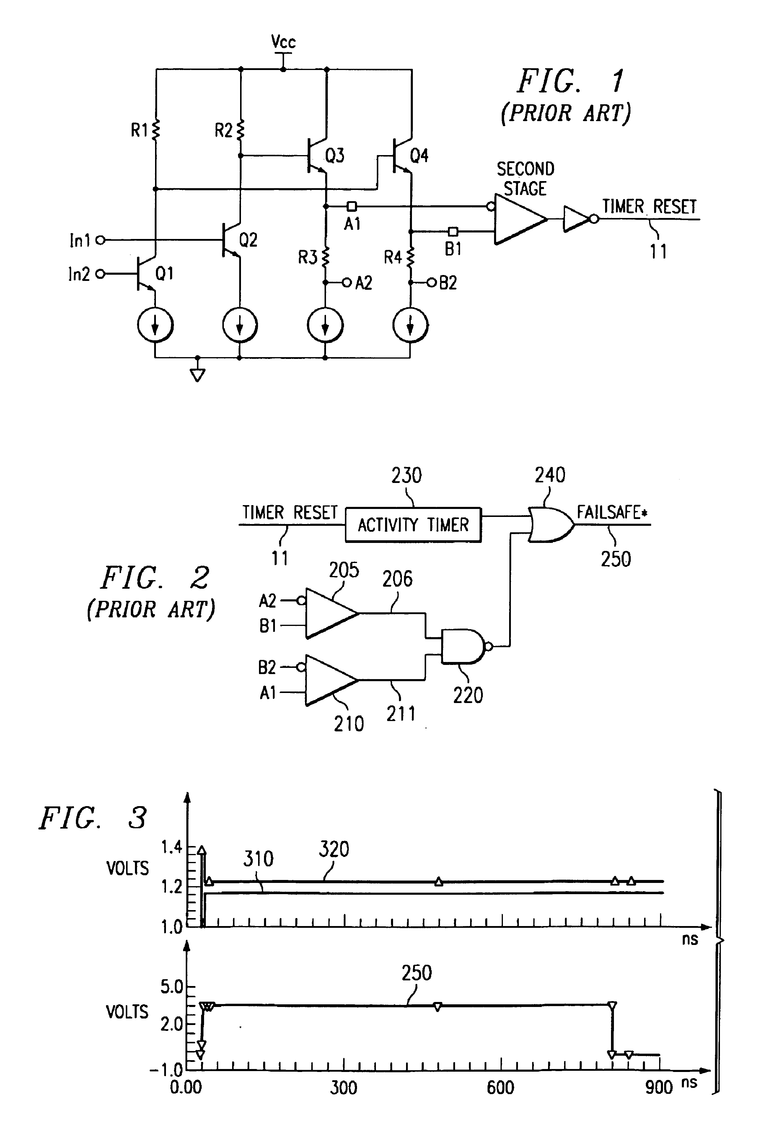
[0019]Typical receiver architectures use one or more stages of low-gain / high-speed NPN input differential amplifiers to amplify an input signal, then a differential to single-ended converter stage to achieve rail-to-rail levels. FIG. 1 illustrates the basic differential input stage architecture.

[0020]Referring to FIG. 1, the differential pair Q1 and Q2 provide gain to the input signal at In1 / In2. The emitters of Q1 and Q2 are respectively coupled to Vc...


PUM


Abstract

The present invention provides a method, system and apparatus for providing failsafe detection for a differential receiver. A bus activity signal (11) is activated when receiving a differential data signal of sufficient amplitude to transition through a predetermined threshold. A failsafe signal (620) indicates a low differential voltage condition. A countdown time period commences (85) upon activation of either signal, and a failsafe condition is determined (89) to exist if the failsafe signal is active (87) when the countdown time period expires (86).

Description

BACKGROUND OF THE INVENTION[0001]1. Technical Field of the Invention[0002]The present invention relates generally to the field of integrated circuits and, more particularly, to a method, system and apparatus of failsafe detection for differential receiver circuits.[0003]2. Background of the Invention[0004]For data transmission it is important to have bus drivers and bus receivers that allow devices to communicate quickly, efficiently, and accurately. This data transmission may occur within a computer system, for example. One common technique for implementation of data transmission within a computer bus uses differential signaling technology to communicate between devices in a computer system. A variety of differential signaling standards exist, such as low voltage differential signaling (LVDS), high voltage differential signaling (HVDS) and others. Of course, such differential signaling may also be used for other long distance data transmission.[0005]Typically, a LVDS driver include...

Claims


Application Information

Patent Timeline
Patent Type & Authority Patents(United States)
IPC IPC(8): H04L25/08H03K19/007H04L25/02
CPCH03K19/007H04L25/08
Inventor TINSLEY, STEVEN J.HWANG, JULIEMORGAN, MARK W.
Owner TEXAS INSTR INC
Why Eureka
Try Eureka