Electronic device

Active Publication Date: 2015-03-05
KYOCERA CORP
View PDF5 Cites 5 Cited by
  • Summary
  • Abstract
  • Description
  • Claims
  • Application Information

AI Technical Summary

Benefits of technology

[0021]According to the present invention, an electronic device in which a touch panel can be vibrated by a plurality of tactile sens

Problems solved by technology

As disclosed in Patent Literature 1, when the touch panel is vibrated by the tactile sensation providing unit, the size of the touch panel that can obtain enough vibration amplitude with one piezoelectric element is limited.
Thus, due to structural restrictions of the circuit, such as current capacity or the like, the

Method used


Image

  • Electronic device
  • Electronic device
  • Electronic device

Examples


Example

First Embodiment

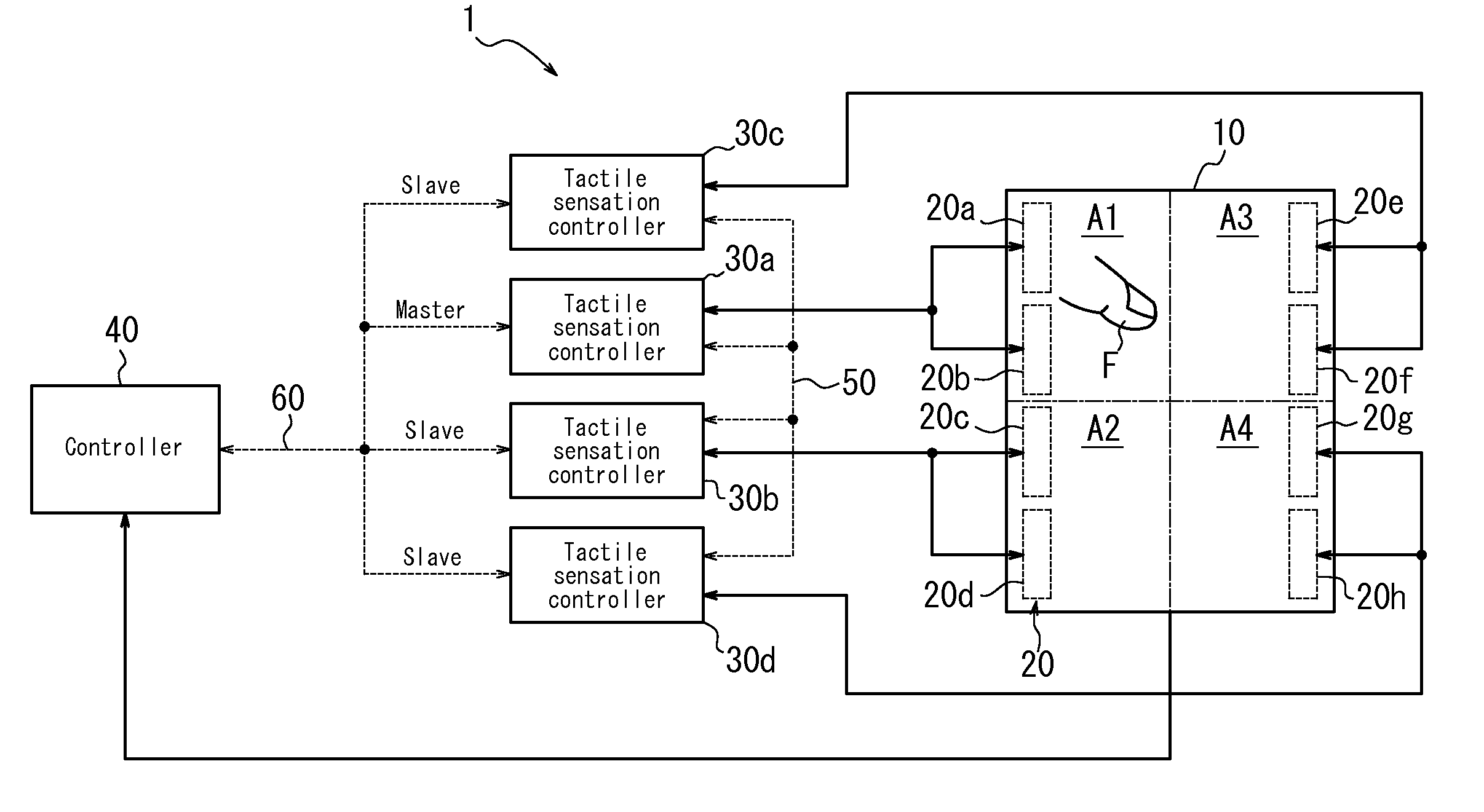
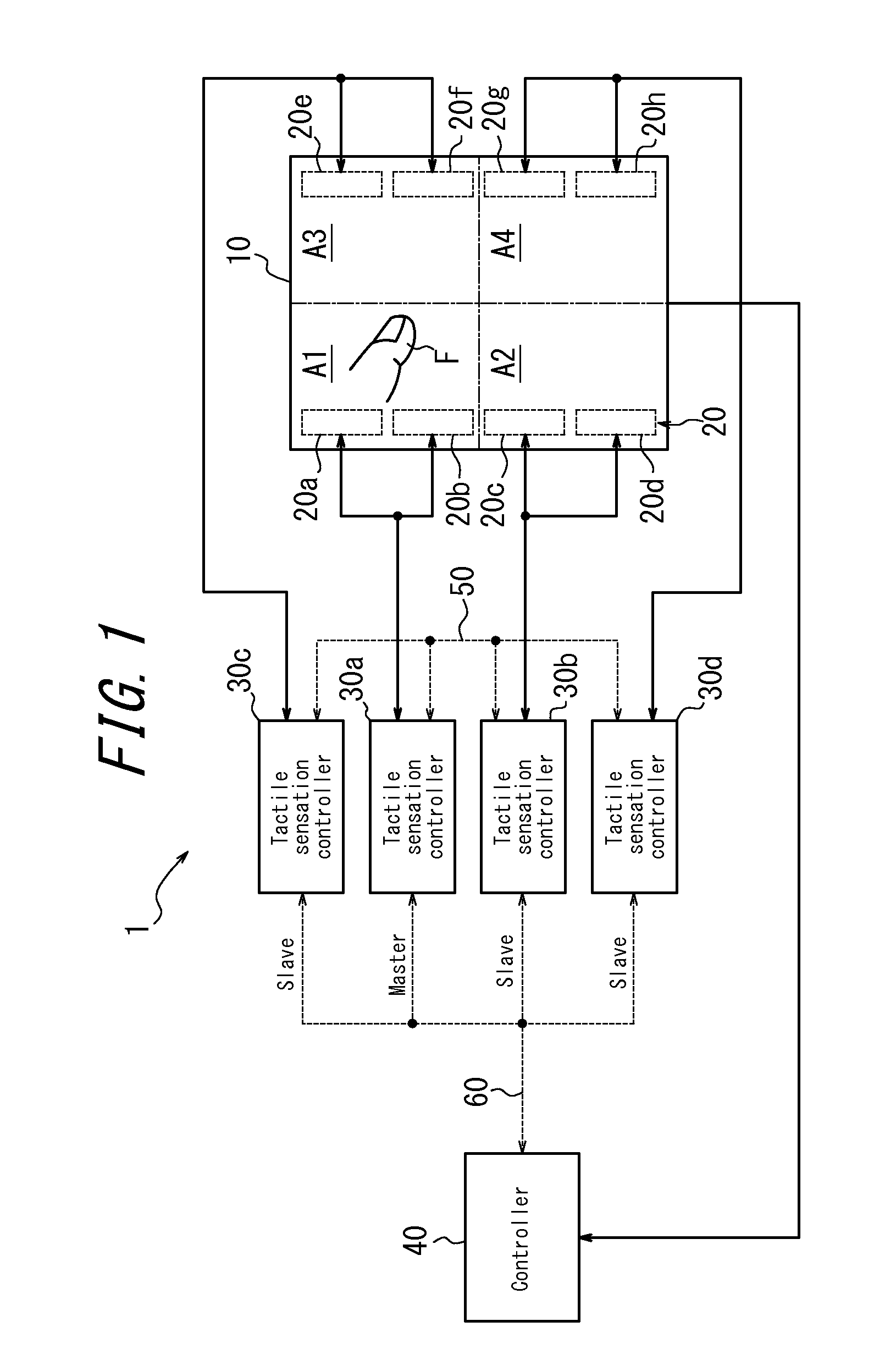
[0025]FIG. 1 is a function block diagram illustrating a schematic configuration of an electronic device according to a first embodiment of the present invention. An electronic device 1 illustrated in FIG. 1 includes a touch panel 10, piezoelectric elements 20, tactile sensation controllers 30 and a controller 40.

[0026]The touch panel 10 is of a known type, such as, for example, a resistive film type, a capacitive type, or the like, and detects a contact of contact object (e.g. a finger or a stylus pen) on an operation face (surface). In addition, the touch panel 10 supplies a signal in response to the detected position of contact to the controller 40. The touch panel 10 is vibratably disposed, for example, on a display screen side of display unit of a liquid crystal display panel (LCD), an organic EL display panel, an electronic paper or the like on which an object that suggests an area to be touched on the operation face to the operator is displayed as an image.

[002...

Example

Second Embodiment

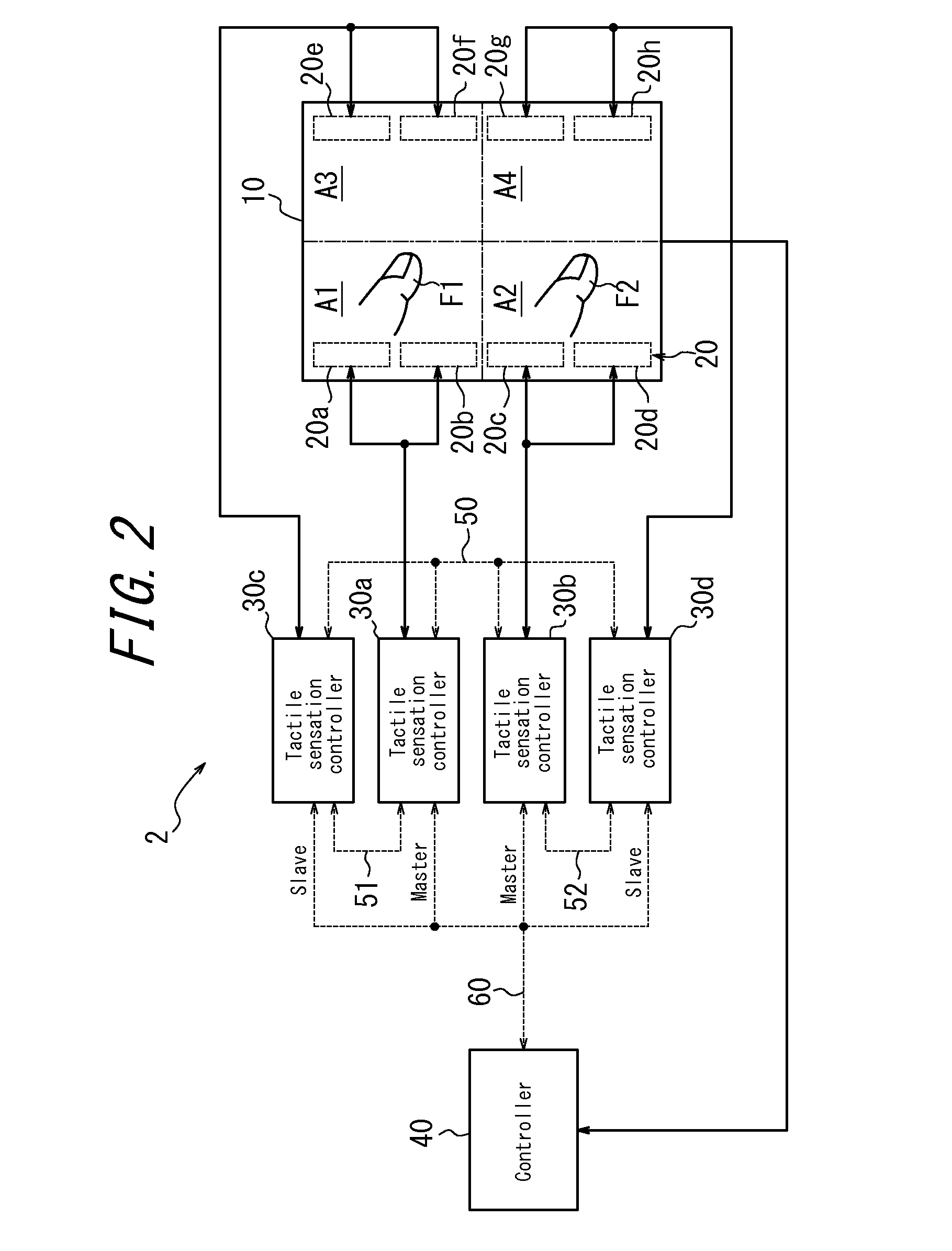
[0040]FIG. 2 is a function block diagram illustrating a schematic configuration of an electronic device according to the second embodiment of the present invention. In the electronic device 2 according to the present embodiment, a function of providing a tactile sensation individually to the two points of contact by multi-touch is added to the electronic device 1 configured as illustrated in FIG. 1. That is, in the electronic device 2 in FIG. 2, to the two points of contact, each on the area A1 or A3 and on the area A2 or A4, drive of the piezoelectric elements 20a and 20b and the piezoelectric elements 20e and 20f, and drive of the piezoelectric elements 20c and 20d and the piezoelectric elements 20g and 20h can be controlled individually.

[0041]Thus, according to the electronic device 2 of the present embodiment, in the configuration illustrated in FIG. 1, the tactile sensation controller 30a that drives the piezoelectric elements 20a and 20b and the tactile sensat...


PUM


Abstract

Provided is an electronic device including a touch panel 10, a plurality of tactile sensation providing units 20a-20h configured to provide a tactile sensation to a contact object F in contact with the touch panel 10, and a plurality of first controllers 30a-30d configured to control drive of the plurality of tactile sensation providing units 20a to 20g, in which one first controller of the plurality of first controllers 30a-30d outputs, to other first controller, a synchronization signal that drives a tactile sensation providing unit associated with the other first controller.

Description

CROSS REFERENCE TO RELATED APPLICATION[0001]The present application claims the priority of Japanese Patent Application No. 2012-069252 filed on Mar. 26, 2012, the content of which is entirely incorporated herein by reference.TECHNICAL FIELD[0002]The present invention relates to an electronic device.BACKGROUND[0003]For example, among electronic devices such as mobile phones, smartphones, tablet terminals, game machines, PCs (Personal Computers), ATM (Automated Teller Machines), automatic ticket vending machines, automatic vending machines, printers, copy machines, fax (facsimile) and home appliances or the like, recently, there is a growing number of electronic devices that detect an input operation by the operator by using a touch panel.[0004]In addition, in such electronic devices, those provided with a tactile sensation providing unit (e.g. piezoelectric element) have been suggested (see, for example, Patent Literature 1). In such electronic devices, when an input operation by whi...

Claims


Application Information

Patent Timeline
IPC IPC(8): G06F3/01G06F3/041
CPCG06F3/0416G06F3/016G06F3/041G06F2203/04105G06F3/04142
Inventor KONO, KENJI
Owner KYOCERA CORP
Why Eureka
Try Eureka