Pressurizer for a rocket engine

a rocket engine and pressurizer technology, applied in the direction of machines/engines, positive displacement liquid engines, pumping pumps, etc., can solve the problems of adding additional mass and complexity to the system, neither is applicable to an expander cycle or staged combustion cycle, etc., to achieve the effect of adding additional mass and complexity

Inactive Publication Date: 2007-03-27
KNIGHT ANDREW F
View PDF18 Cites 15 Cited by
  • Summary
  • Abstract
  • Description
  • Claims
  • Application Information

AI Technical Summary

Benefits of technology

[0008]Another problem with the Sobey and Lanning systems is that both require an externall

Problems solved by technology

A problem with the Sobey and Lanning systems is that neither is applicable to an expander cycle or staged combustion cycle.
Another problem with the

Method used


Image

  • Pressurizer for a rocket engine
  • Pressurizer for a rocket engine
  • Pressurizer for a rocket engine

Examples


Embodiment Construction

[0046]In the following description, the use of “a,”“an,” or “the” can refer to the plural. All examples given are for clarification only, and are not intended to limit the scope of the invention.

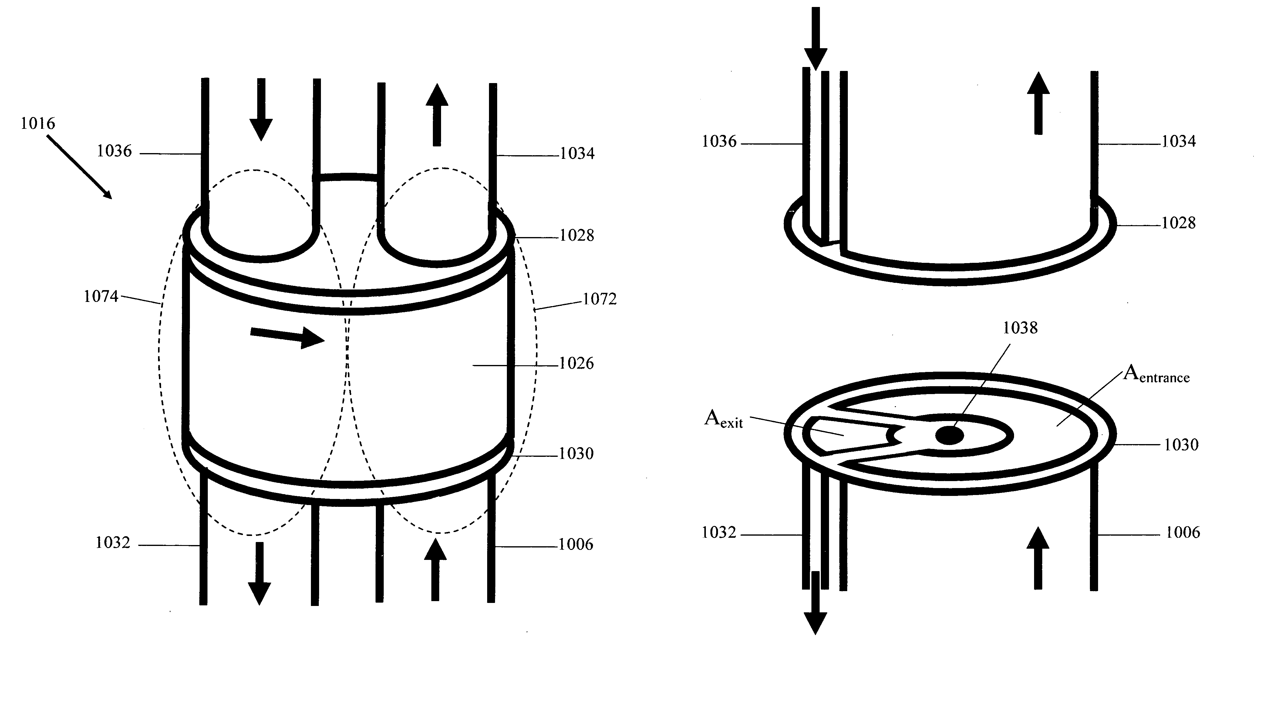
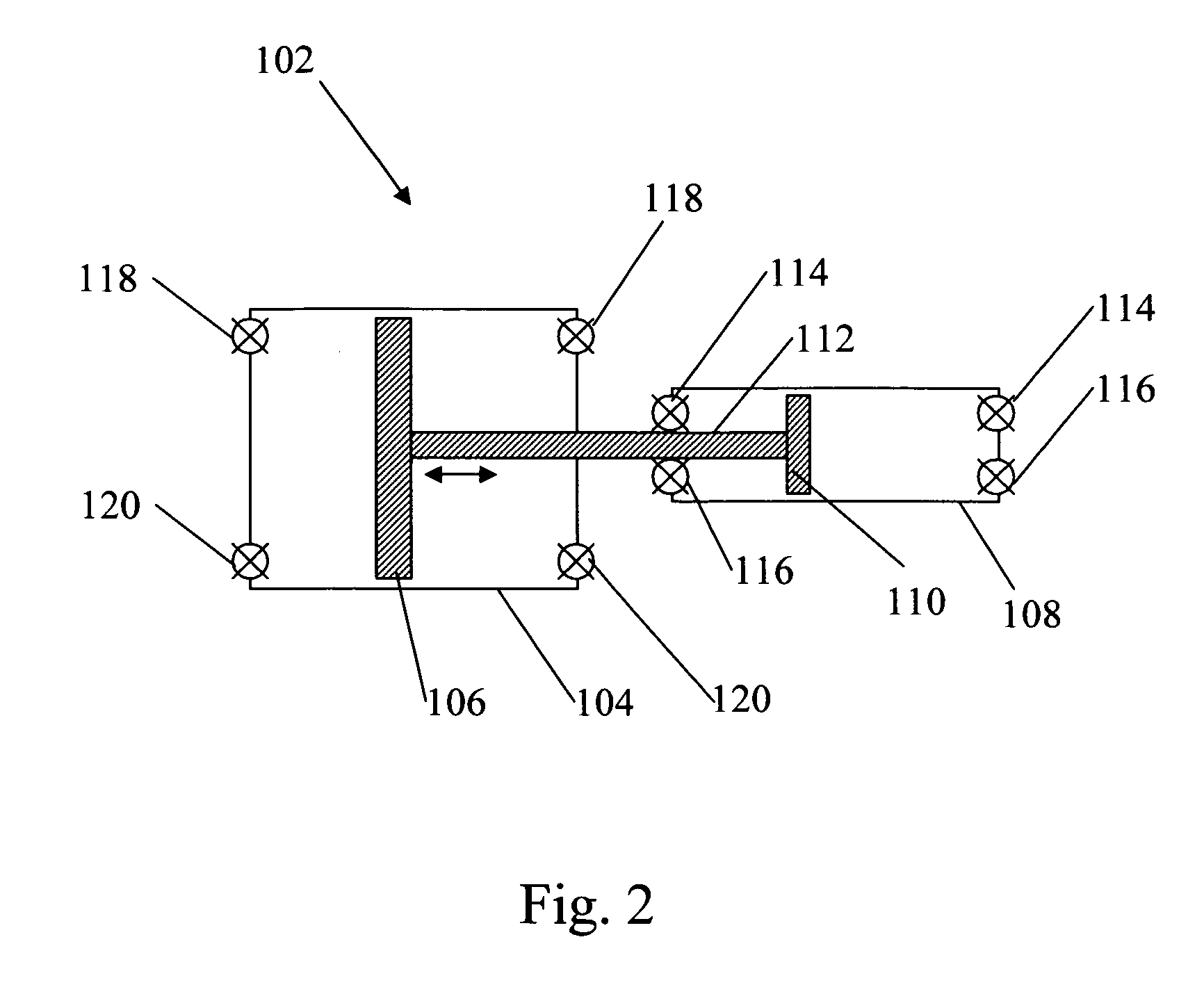
[0047]Referring now to FIG. 1, a piston pump 2 comprises a low-pressure fluid inlet 4, a high-pressure fluid outlet 6, a pressurant inlet 8, a pressurant outlet 10, a first pressure vessel 12 containing a preferably linearly movable first piston 14, and preferably two second pressure vessels 16 each containing a preferably linearly movable second piston 18, where the first piston 14 is connected to the two second pistons 18 via two connecting rods 20. Thus, all three pistons 14, 18 are movable together in the linear directions indicated by the array. The first and second pressure vessels 12, 16 are separated by walls 42, through which connecting rods 20 may slide with a relatively tight seal, to prevent pressurant located within the first pressure vessel 12 from leaking to one of the second ...


PUM


Abstract

A pump for pressurizing a fluid includes an engine portion including a first pressure vessel, a first piston movable inside the first pressure vessel, at least two pressurant entrance valves connected to the first pressure vessel, and at least two pressurant exit valves connected to the first pressure vessel. The valves are configured to be opened and closed automatically and directly as a function of a position of the first piston inside the first pressure vessel. The valves are also configured to be automatically opened and closed out of phase with each other. The pump also includes a pump portion including a second pressure vessel, a second piston connected to the first piston and movable inside the second pressure vessel, at least two fluid entrance valves connected to the second pressure vessel, and at least two fluid exit valves connected to the second pressure vessel.

Description

REFERENCE TO RELATED APPLICATIONS[0001]This application is a Continuation-in-Part (CIP) of U.S. patent application Ser. No. 10 / 629,685, entitled “Pressurizer For a Rocket Engine,” filed Jul. 30, 2003 (now U.S. Pat. No. 7,082,750), which is a CIP of U.S. patent application Ser. No. 10 / 214,706, entitled “Pressurizer For a Rocket Engine,” filed Aug. 9, 2002 (now U.S. Pat. No. 6,751,945), which is a CIP of U.S. patent application Ser. No. 09 / 878,293, entitled “Pressurizer For a Rocket Engine,” filed Jun. 12, 2001 (now U.S. Pat. No. 6,499,288), the disclosures of which are herein incorporated by reference.BACKGROUND[0002]Rocket engines require propellants to be fed to them at very high pressures. This has historically been accomplished in two general ways: first, with the use of a pressurized fluid, such as high pressure helium; and second, with the use of a pump.[0003]In the first way (e.g., a “blowdown” system), a pressurized fluid, such as helium, is added directly to the propellant t...

Claims


Application Information

Patent Timeline
IPC IPC(8): F02K9/00F02K9/42F02K9/72
CPCF02K9/46F04F13/00F04B9/133F02K9/50
Inventor KNIGHT, ANDREW F.
Owner KNIGHT ANDREW F
Why Eureka
Try Eureka