Engine cooling structure, and engine incorporating same

a technology of engine cooling structure and cooling structure, which is applied in the direction of engine cooling apparatus, machine frames, casings, etc., can solve the problems of large distance between the water pump or the like and the water jacket, complicated piping construction around the engine, and the above-described cooling structure is problematic, so as to reduce the amount of space occupied, prevent the enlargement of the cover member, and simplify the layout of the exhaust pipe

Active Publication Date: 2007-03-27
HONDA MOTOR CO LTD
View PDF7 Cites 14 Cited by
  • Summary
  • Abstract
  • Description
  • Claims
  • Application Information

AI Technical Summary

Benefits of technology

[0015]With the engine cooling structure of the first aspect of the invention, since the positions of the water pump and the thermostat for circulating the coolant have been moved to the outside of the crankcase of the engine, where it is easy to secure the required mounting space, it is possible to make the space occupied by the cooling structure itself compact. Accordingly, as compared to the conventional cooling structure, in which the water pump and the thermostat are disposed on a side of the cylinder head, the cooling structure can increase the degree of freedom of layout around the cylinder head by keeping the projection amount on the side of the cylinder head small.
[0016]Moreover, in the engine cooling structure of the first aspect of the invention, the water pump and the thermostat are provided on the cover member installed on the outside of the crankcase of the engine. In addition, the coolant passage, which communicates with the water jacket through the water pump from the thermostat, is integrally formed in the cover member. Thus, the need for the work of, for example, connecting a pipe or the like to be the coolant channel to the water pump inside the cover member is eliminated, complication in the piping construction is prevented, and the number of assembly steps is reduced.
[0018]In other words, with the engine cooling structure of the second aspect of the invention, the room below the generator is effectively utilized as a space for disposing the water pump, and the cooling structure is arranged efficiently in terms of space.
[0019]With the engine cooling structure of the third aspect of the invention, the first and second passages to be the coolant passage are arranged compactly, and it is therefore possible to prevent the enlargement of the cover member and reduce the amount of space occupied.
[0020]With the engine cooling structure of the fourth aspect of the invention, the water pump, the thermostat, and the like do not interfere with the layout of the exhaust pipe, and it is possible to place the exhaust pipe within such a region that does not affect the banking angle of the vehicle body. Thus, the layout design of the exhaust pipe is simplified.

Problems solved by technology

However, the above-described cooling structure is problematic since, by mounting the cooling structure at this location, the cooling structure projects outwardly from the vehicle body.
However, if the positions of the water pump and the thermostat are merely moved to the periphery of the crankcase, the distance between the water pump or the like and the water jacket becomes large, and the piping construction installed around the engine becomes complicated.
Thus, a new problem arises that the number of assembly steps for installing piping increases.

Method used


Image

  • Engine cooling structure, and engine incorporating same
  • Engine cooling structure, and engine incorporating same
  • Engine cooling structure, and engine incorporating same

Examples


Embodiment Construction

[0035]A detailed description will be given below of a preferred embodiment of an engine cooling structure according to the present invention with reference to the drawings.

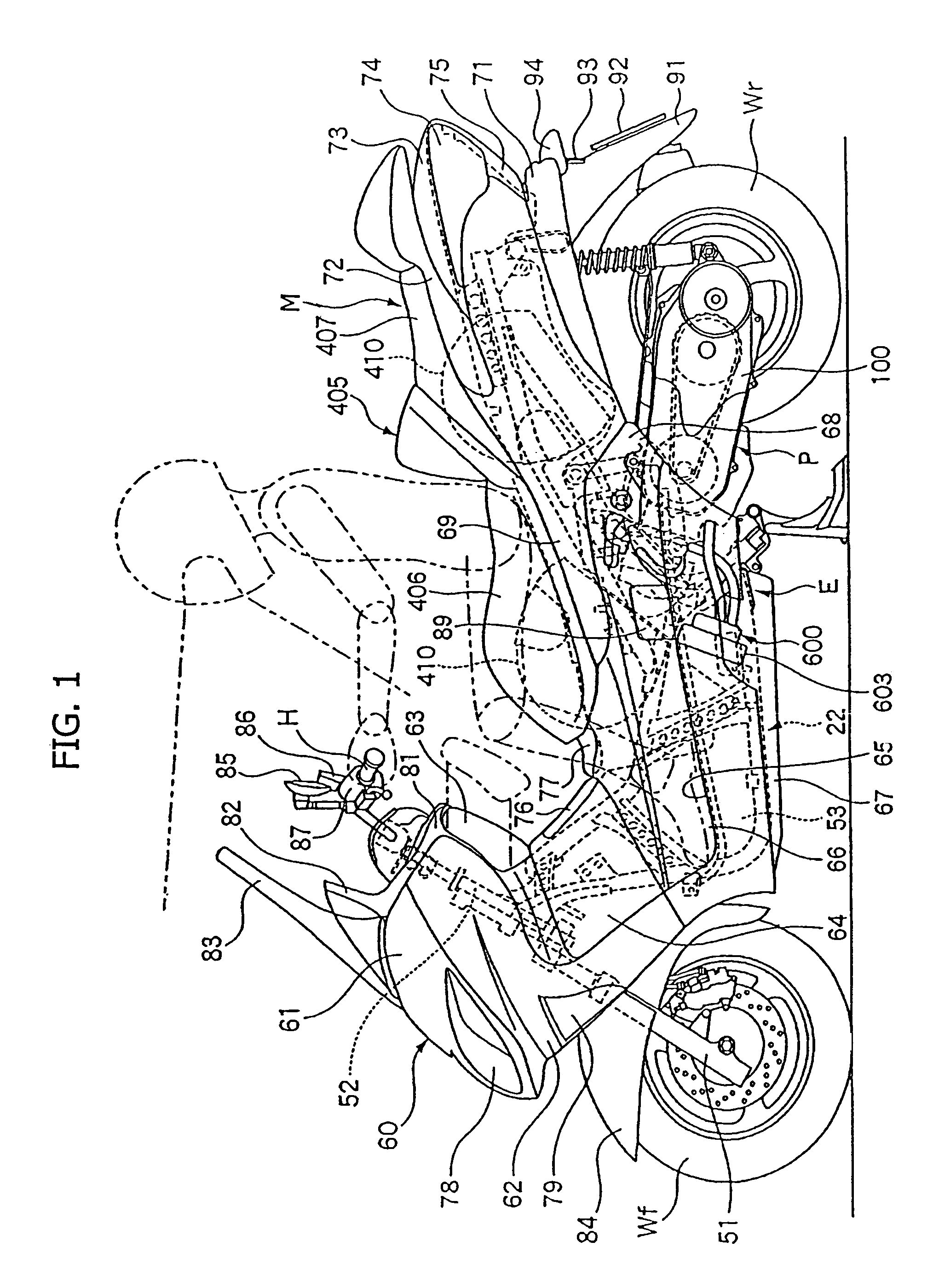
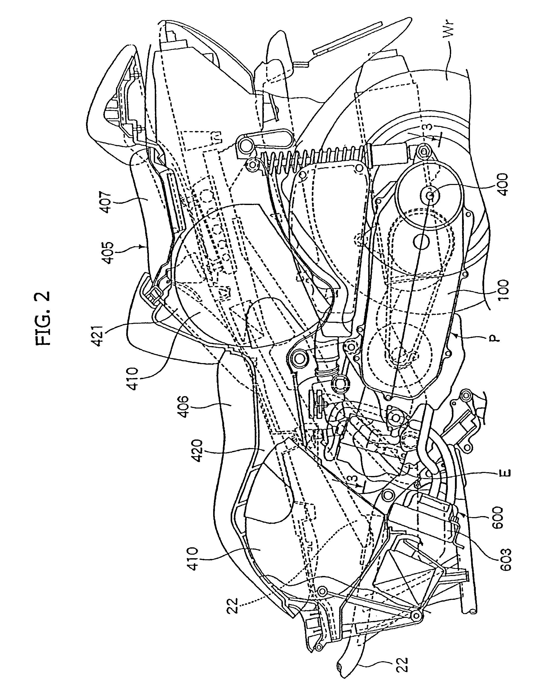
[0036]FIGS. 1 to 13 show a motorcycle incorporating a cooling structure according to a first embodiment of the present invention.

[0037]In the scooter-type motorcycle M shown in FIG. 1, a swing-type power unit P is disposed at a position which is below a seat 405, and which is between a front wheel Wf steered by a steering handle H and a rear wheel Wr, which is a driving wheel.

[0038]A body frame 22 of the motorcycle M includes, at the front end thereof, a front fork 51 rotatably supporting the front wheel Wf and a head pipe 52 pivotally and steerably supporting the steering handle H connected to the front fork 51. In addition, the power unit P, supporting the rear wheel Wr at the rear end of the body frame 22, is pivotally supported in the middle portion in the fore-and-aft direction of the body frame 22, so as to ...


PUM


Abstract

An engine cooling structure for a water cooled engine includes water pump and a thermostat. The water pump pumps coolant to a water jacket of the engine. The water pump and thermostat are provided on a cover member installed on an outside of a crankcase of the engine, and a coolant passage, which communicates with the water jacket through the water pump from the thermostat, is integrally formed in the cover member, so as to obtain arrangement of the cooling structure that is efficient in terms of space. The engine cooling structure increases the degree of freedom of layout around a cylinder head by keeping the projection amount on a side of the cylinder head small, simplifies the piping construction, and reduces the number of assembly steps.

Description

CROSS-REFERENCE TO RELATED APPLICATIONS[0001]The present invention claims priority under 35 USC 119 based on Japanese patent application No. 2004-288195, filed on Sep. 30, 2004. The subject matter of this priority document is incorporated by reference herein.BACKGROUND OF THE INVENTION[0002]1. Field of the Invention[0003]The present invention relates to an engine cooling structure used in a water-cooled engine for a motorcycle or the like. More particularly, the present invention relates to an engine cooling structure including a water pump for pumping coolant to a water jacket of the engine, and a thermostat which switches channels through which the coolant is routed on its way back from the water jacket to the water pump, according to the temperature of the coolant.[0004]2. Background Art[0005]Water cooled engines are well known. One known engine cooling structure used in a water-cooling engine has a configuration including: a water pump pumping coolant to the water jacket of the ...

Claims


Application Information

Patent Timeline
Patent Type & Authority Patents(United States)
IPC IPC(8): F01P7/14F01P5/10F02B67/00
CPCF01P5/10F01P11/04F01P7/16F01P2050/16
Inventor WACHIGAI, KAROUOKI, KENJI
Owner HONDA MOTOR CO LTD
Why Eureka
Try Eureka