Method for controlling several pumps

a technology for controlling several pumps and pumping, which is applied in the direction of pump control, non-positive displacement fluid engine, pump control, etc., can solve the problems of making assembly and operation of the pumps more difficult, and achieve the effect of simplifying and ensuring the control of alternating operation of several pumps

Active Publication Date: 2007-03-27
GRUNDFOS
View PDF8 Cites 67 Cited by
  • Summary
  • Abstract
  • Description
  • Claims
  • Application Information

AI Technical Summary

Benefits of technology

[0004]It is therefore the object to provide a method for controlling several pumps in a pump sump as well as a correspondingly designed pump, which require no additional control and permits a simplified and failure-secure control of an alternating operation of several pumps.
[0009]At the same time the pumps do not communicate with one another and are not connected to one another by way of a central control means. Rather the individual pumps comprise control means which are independent of one another. Merely by way of the intelligent control of each individual pump one succeeds in running the pumps alternately despite the fact that they do not communicate with one another and are not centrally controlled. Since for controlling the several pumps one requires no connection between the pumps and no central control means, the application and assembly of such pumps is extremely simple. The pumps merely need to be applied into a pump sump without the pumps for example having to be connected to one another for example by way of control conduits. Subsequently the alternating operation of the individual pumps is automatically set, without further setting work being required. At the same time the control of the individual pumps is preferably designed such that each pump is also capable of functioning alone, i. e. may be operated in a pump sump without further pumps. In this manner one creates a universally applicable pump.
[0011]Preferably the fluid level threshold value for each pump after the running of a further pump is reduced in steps by a predefined value. This has the effect that the fluid level threshold value is further reduced after each running of a further pump so that it again approaches the initial threshold value. By way of this stepped reduction of the fluid level threshold value the fluid level threshold value of each pump will again some time reach a value which is smaller than the fluid level threshold values of the remaining pumps so that on increase of the fluid level this first pump again is set in operation. By way of the cyclic increase and subsequent stepped reduction of the fluid threshold values it is achieved that the pumps are always alternately set into operation.
[0015]x+Δ⁢⁢x⁢⁢x⁢1nwherein x corresponds to the initial threshold value; Δx the amount by which the fluid level threshold value is increased with respect to the initial threshold value, and n is the number of previously run pumps. This is a preferred control of the pumps with which the reduction of the fluid level threshold value is effected such that the fluid level threshold value after each running of a further pump further approximates the initial threshold value. The fluid level threshold reached on reduction however always lies above the initial threshold value, by which means it is achieved that if a further or new pump is applied into the pump sump, this has the lowest fluid level threshold value, specifically the initial threshold value and thus will run first. The stepped reduction further has the effect that of the pumps which have already run the respective earlier run pump has a lower fluid level threshold value than the later run pumps so that this pump is also firstly again set into operation. With this it is ensured that the individual pumps are always actuated cyclically in succession and thus are uniformly burdened.

Problems solved by technology

The installation of such a central control renders the assembly and operation of the pumps more difficult.
Furthermore the fact that a pump which is not next in line is not switched on even when achieving its switching threshold leads to problems when the respective pump which is next in line in alternating operation fails.

Method used


Image

  • Method for controlling several pumps
  • Method for controlling several pumps
  • Method for controlling several pumps

Examples


Embodiment Construction

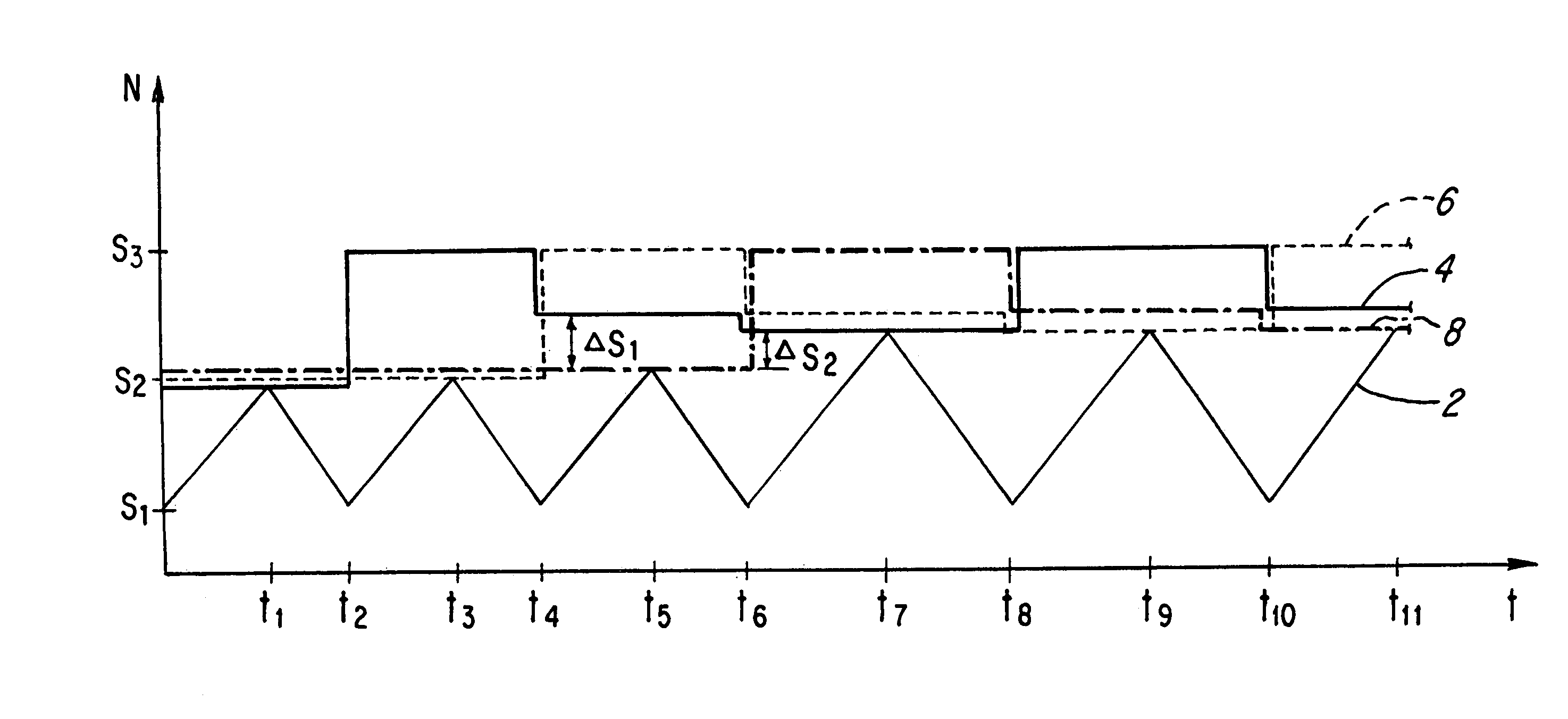
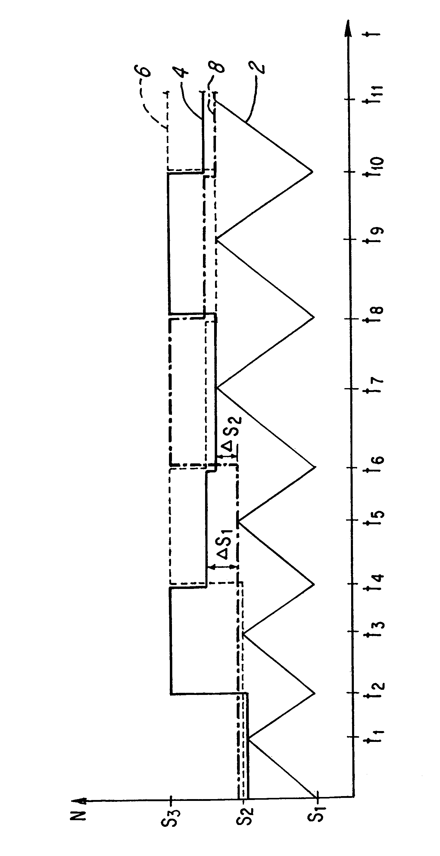
[0029]In the attached diagram there is schematically shown the course of the fluid level N in a pump sump as well as the threshold values of the applied pumps over the time t. The lower unbroken line 2 represents the fluid level in the pump sump over the time t. The unbroken line 4, the dashed line 6 as well as dot-dashed line 8 in each case symbolise the fluid level threshold value of a pump at which the respective pump is activated. In its basic condition each pump has three fluid level threshold values S1, S2 and S3. At the same time the threshold value S2 corresponds to an initial threshold value which is set in the basic or delivered condition of the pump and when it is reached the pump is activated via a level sensor. The threshold value S1 is the threshold value which when reached deactivates the pump. The threshold value S3 represents a second start threshold value at which when reached each pump is in any case activated, independently of the remaining control. S3 is thus an...


PUM


Abstract

The invention relates to a method for controlling several pumps in a pump sump, with which each pump comprises a switch which switches on the pump and each pump after its running is first blocked and depending on the running of the further pumps in the pump sump is released again. The invention further relates to a pump for carrying out this method.

Description

BACKGROUND OF THE INVENTION[0001]The invention relates to a method for controlling several pumps as well as a correspondingly designed pump.[0002]There are known pumps, in particular submersible pumps which are applied in pump sumps in order to pump away the fluid collected in the pump sump given a predefined fluid level. With such a pump sump one often uses several pumps. With the application of several pumps it is to be ensured that the pumps are uniformly operated in capacity so that the pumps also wear uniformly. The alternating activation of the individual pumps requires a central control which alternately switches the pumps on and off. The installation of such a central control renders the assembly and operation of the pumps more difficult.[0003]From DE 199 27 365 C2 there is known a control of several pumps in a common pump sump, according to which even when achieving a predefined switching threshold is not switched on if it is not the turn of the respective pump in alternati...

Claims


Application Information

Patent Timeline
Patent Type & Authority Patents(United States)
IPC IPC(8): F04B49/00F04D15/02
CPCF04D15/029
Inventor NYBO, PETER JUNGKLASILVES, LASSEYLI-KORPELA, HEIKKI
Owner GRUNDFOS
Why Eureka
Try Eureka