Golf ball with improved directional stability in putting stroke

a golf ball and directional stability technology, applied in the field of golf balls, can solve the problems of increasing the difficulty of controlling the direction of the ball, reducing the accuracy of the putting stroke, so as to prevent the reduction of the flight distance and minimize the negative effect of aerodynamic

Inactive Publication Date: 2007-03-27
SUNRISE ENTERPRISE
View PDF17 Cites 16 Cited by
  • Summary
  • Abstract
  • Description
  • Claims
  • Application Information

AI Technical Summary

Benefits of technology

[0015]It is not possible to control the ball, which has been hit, to be stopped such that the undimpled hit portion of the ball is positioned in a desired position relative to a target hole. However, it is possible to adjust the position of the undimpled hit portion of the ball relative to the target hole when the ball is replaced at a stopped position on a putting green, on which the ball is allowed to be lifted or picked up after the stopped position is marked by placing a ball-marker (e.g., a small coin or other similar object) immediately behind the ball. Thus, the ball can be put on the putting green such that the center of the hit portion is positioned on a predetermined line to the target hole and such that the center of the hit portion is remoter from the target hole than the center of the ball, so that the undimpled hit portion serves as the pressed area to be pressed by the club face in a putting stroke.
[0016]It might be possible to putt a conventional ball (which does not have a particular portion equivalent to the hit portion) in a desired direction, by pressing a suitable point of the outer surface of the conventional ball by a putter face such that the dimples are distributed evenly in the entirety of the pressed area, namely, such that the center of balance of the contact area substantially coincides with the center of the pressed area. However, the diameter of the pressed area in a putting stroke is so small that the distribution of the dimples or the center of balance of the contact area is easily changed or displaced even with a small amount of deviation of an actually pressed point from the above-described suitable point. Thus, for making the conventional ball run in a desired direction, it is necessary to accurately locate the suitable point and then press the ball precisely at the suitable point, which are extremely difficult to be done by a golf player during his putting play.
[0017]According to one advantageous arrangement of the first preferred form of the invention, the above-described at least one hit portion consists of a plurality of hit portions which are positioned relative to each other such that a center of balance of the plurality of hit portions coincides with the center of the golf ball. This balanced arrangement of the hit portions permits the golf ball to enjoy an aerodynamic uniformity, during its flight in a golf course, as a conventional ball which does not have the undimpled hit portions, thereby minimizing a negative aerodynamic effect and preventing a reduction of the flight distance.
[0018]The above object may be also achieved according to a second preferred form of the present invention, which provides a golf ball having a predetermined radius, and a spherical outer surface with a multiplicity of dimples formed therein, wherein the spherical outer surface has at least one hit portion which has a diameter of 5–15 mm and within which the dimples are absent except a single one of the dimples that is located at a central part of the hit portion.
[0019]In the hit portion of the golf ball of the second preferred form of the invention, the single dimple is located at the central part of the hit portion, and an annular part of the hit portion surrounding the central part constitutes a part of the spherical outer surface. When the golf ball of the second preferred form of the invention is pressed at the hit portion by a club face, the annular part of the hit portion becomes substantially flat with substantially no protrusions and recesses therein, and is brought into contact with the club face, so that the center of distribution of the reaction force of the ball substantially coincides with the center of the pressed area. In other words, the hit portion, i.e., the single-dimple portion having the diameter of at least 5 mm provides an annular-shaped flat portion having a diameter of at least 5 mm, in the pressed area which has a diameter of about 5–15 mm in a putting stroke, whereby a sufficiently increased contact area actually brought in contact with the club face is provided in the pressed area so that the center of balance of the contact area substantially coincides with the center of the pressed area.
[0020]Such a substantial coincidence of the center of distribution of the reaction force and the center of the pressed area is obtained, even where the center of the pressed area does not exactly coincide with the center of the hit portion, or even where the diameter of the pressed area is made larger than the diameter of the hit portion, namely where some part of the pressed area is not brought in contact with the club face. Therefore, the reaction force acts in a direction substantially parallel to a direction in which the club is swung or stroked, so that the ball is made to run in a desired direction substantially equal to the direction in which the club is stroked.

Problems solved by technology

However, even if the putter is swung or stroked straight and parallel to the determined line, the ball does not necessarily run along the line, resulting in difficulty of making the ball run in the desired direction with a sufficient stability.
Such a difficulty of controlling the direction of the ball tends to be increased, particularly, in a putting stroke with what is called a “soft touch”, in which the ball is hit with a comparatively small hitting force.
Various experiments conducted by the present inventors for studying about the above-described problem revealed that dimples formed in the outer surface of the ball make it difficult to putt the ball in the desired direction with a sufficient stability.
The uneven distribution of the dimples within the pressed area means that the center of balance of the contact area of the pressed area which is actually brought into contact with the club face, i.e., the center of distribution of the reaction force applied to the club face from the ball deviates from the center of the circular-shaped pressed area, whereby the reaction force does not act in a direction parallel to a direction in which the club is swung or stroked, resulting in difficulty of making the ball run in the desired direction with a sufficient stability.

Method used


Image

  • Golf ball with improved directional stability in putting stroke
  • Golf ball with improved directional stability in putting stroke
  • Golf ball with improved directional stability in putting stroke

Examples


first embodiment

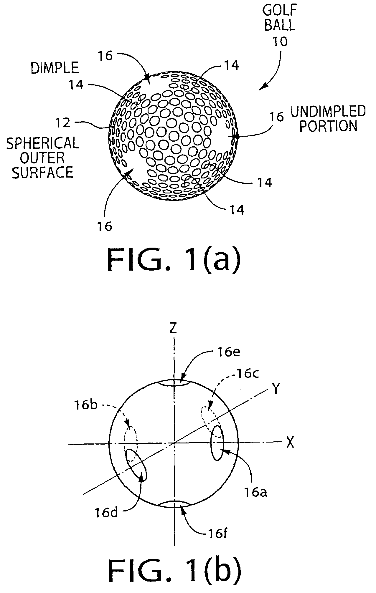
[0060]Referring first to FIGS. 1(a) and (b), there is shown a golf ball 10 of this invention which is constructed in accordance with golf international standards. The golf ball 10 has a predetermined radius, and is made of a rubber material similar to that used in conventional golf balls to have a certain degree of elasticity. The golf ball 10 has, in its spherical outer surface 12, a multiplicity of shallow depressions or dimples 14 formed to be arranged according to a predetermined pattern. Each of the dimples 14 has a substantially circular shape whose diameter is about 1–3 mm.

[0061]In the major portion of the spherical outer surface 12 of the ball 10, the spacing interval between adjacent ones of the dimples 14 is not larger than, for example, about 1–2 mm. However, in local portions of the spherical outer surface 12, the spacing interval between the adjacent dimples 14 is increased to, for example, about 10 mm. That is, the spherical outer surface 12 has, in its local portions,...

second embodiment

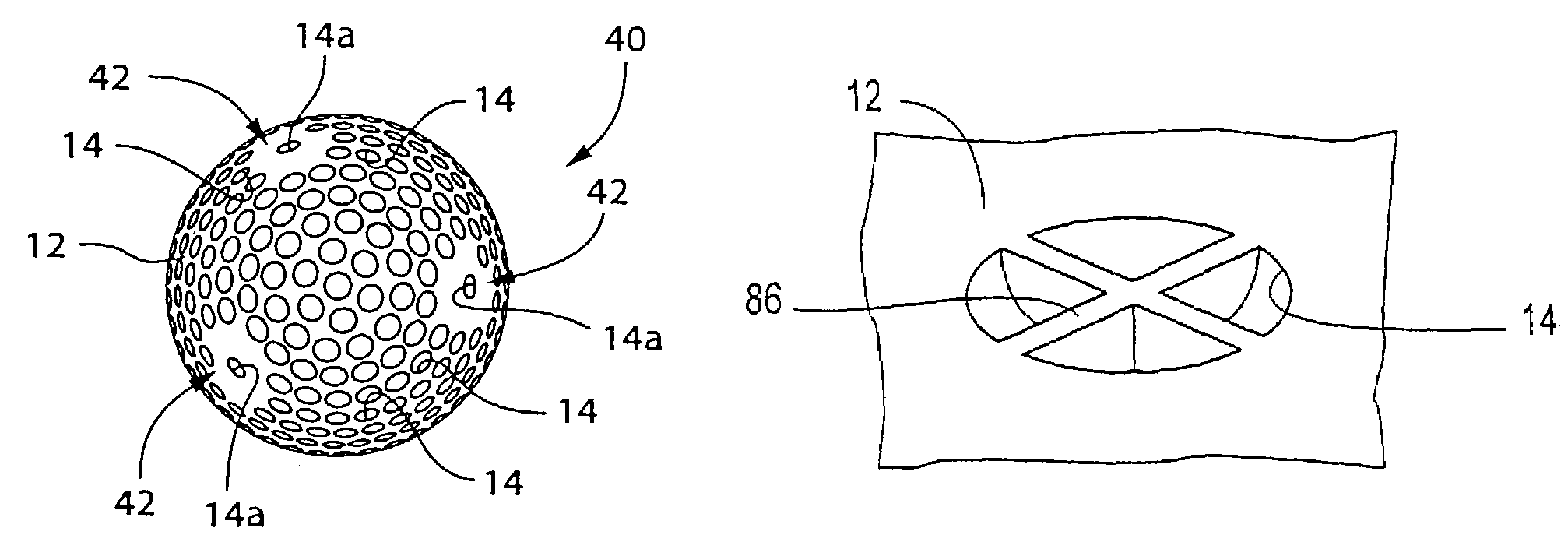
[0073]FIGS. 6 and 7 show a golf ball 40 of the second embodiment which has single-dimple portions 42 in place of the undimpled portions 16. That is, the spherical outer surface 12 of the ball 40 has six single-dimple portions 42 which are arranged to be symmetrical with each other with respect to the center of the golf ball 40, in addition to the major portion in which the spacing interval between adjacent ones of the dimples 14 is not larger than about 1–2 mm. In each of the six single-dimple portion 42 (three of which are invisible in FIG. 6), the dimples 14 are absent except a single one 14a of the dimples 14 which is located at a central part of each of the single-dimple portions 42. Each single-dimple portion 42 is dimensioned such that a circle having a diameter of about 10 mm is inscribed in the single-dimple portion 42. The dimple 14a located at the central part of the single-dimple portion 42 has a diameter of about 1–3 mm and the same shape as the other dimples 14, and has...

third embodiment

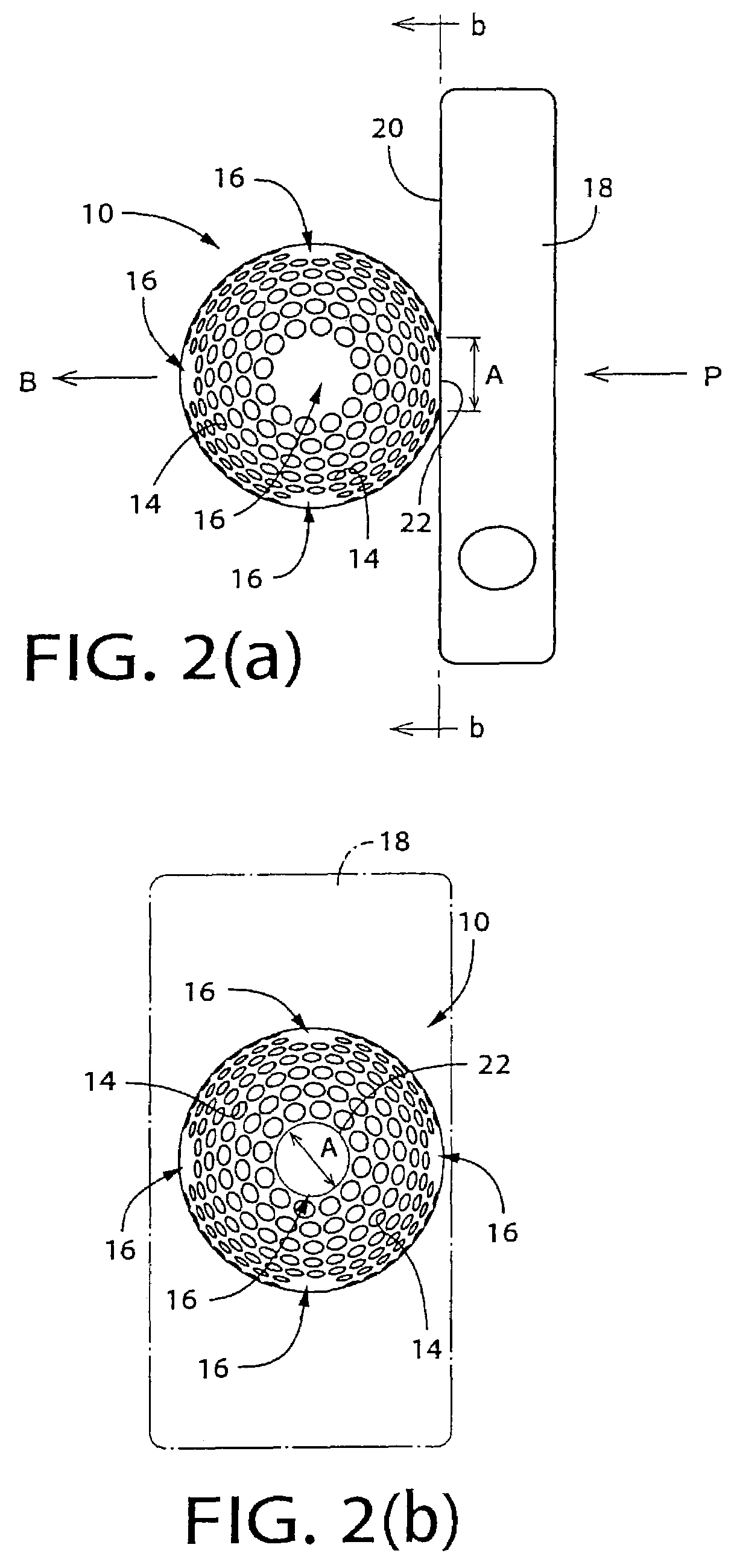
[0081]In the golf ball 50 of the present third embodiment, the grooves 52 of the lattice-arranged groove portion 54 are arranged in a lattice so as to be symmetrical with each other. The symmetrical arrangement of the grooves 52 further reduces the deviation of the center of distribution of the reaction force from the center of the pressed area 22, where the center of the pressed area 22 is deviated from the center of the lattice-arranged groove portion 54, i.e., where the golf ball 50 is not hit at the center of the lattice-arranged groove portion 54. Thus, the symmetrical arrangement of the grooves 52 is effective to further improve the directional stability of the ball 50 in a putting stroke.

[0082]FIG. 9 shows a golf ball 60 of the fourth embodiment of the present invention. The golf ball 60 has annular groove portions 58 in place of the lattice-arranged groove portions 54. That is, the spherical outer surface 12 of the golf ball 60 has six annular groove portions 58 (three of wh...


PUM


Abstract

A golf ball having a predetermined radius, and a spherical outer surface with a multiplicity of dimples formed therein. A protrusion is formed in each of the dimples which are located in hit portions having a diameter of 5–15 mm, or alternatively, is formed in each of all the dimples. The protrusion has a distal end whose radial distance from the center of the golf ball is equal to the predetermined radius of the golf ball. The protrusion has a partition wall which divides a space in each dimple into a plurality of segmental spaces. The protrusion may have two partition walls which are perpendicular to each other and intersect at right angles for dividing a space in each of the dimples into four segmental spaces.

Description

[0001]This is a Continuation-In-Part application of application Ser. No. 09 / 778,813, filed on Feb. 8, 2001 now abandoned.BACKGROUND OF THE INVENTION[0002]1. Field of the Invention[0003]The present invention relates in general to improvements in a golf ball.[0004]2. Discussion of the Related Art[0005]There is known a golf ball consisting principally of, for example, a spherical body having a certain degree of elasticity, and a rubber-made cover covering an outer surface of the spherical body. The spherical body includes a rubber-made, spherical core which is wound with a rubber thread or other fiber. In an outer surface of the rubber-made cover, there are formed a multiplicity of shallow recesses or dimples each having, in general, a substantially circular shape whose diameter is about 1–3 mm, such that the dimples are distributed substantially evenly over the entire outer surface of the cover. The dimples assist the ball, when hit by a club, to fly high and straight in a golf course...

Claims


Application Information

Patent Timeline
Patent Type & Authority Patents(United States)
IPC IPC(8): A63B37/12A63B37/00A63B37/14A63B45/00
CPCA63B37/0004A63B37/0005A63B37/0007A63B37/002A63B37/0011A63B37/0012A63B37/001
Inventor HANADA, HIDETOSUZUKI, YUTAKAYOSHIDA, KIMIYO
Owner SUNRISE ENTERPRISE
Why Eureka
Try Eureka