

Apparatus and method using it for detecting and displaying form of insertion part of endoscope inserted into body cavity
- Summary
- Abstract
- Description
- Claims
- Application Information
AI Technical Summary
Benefits of technology
Problems solved by technology
Method used
Image

Examples
first embodiment
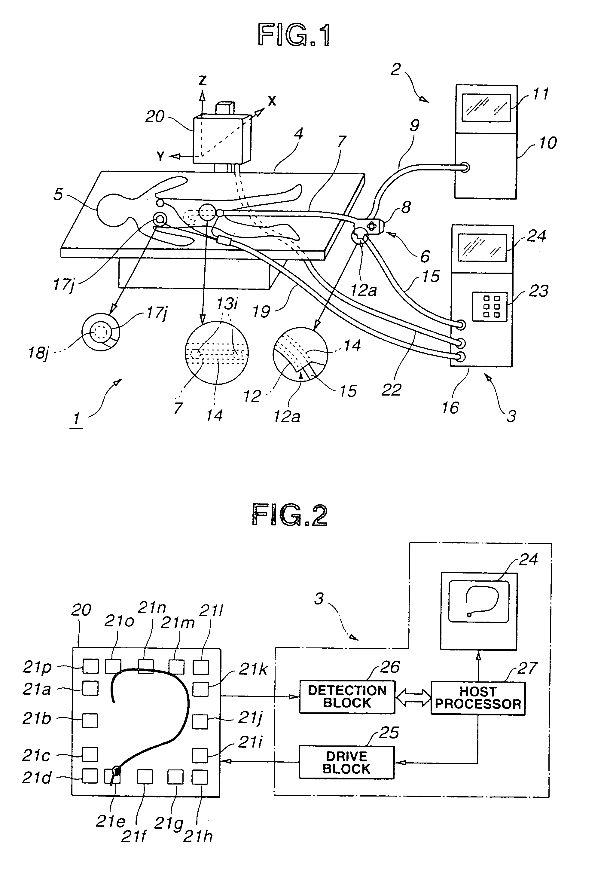
[0138]the present invention will be described with reference to FIG. 1 through FIG. 5.
[0139]As shown in FIG. 1, an endoscope system 1 consists generally of an endoscopic imaging system 2 used for endoscopic examination, and a shape-of-endoscope detecting apparatus 3 used to assist in endoscopic examination and to detect the shape of an inserted portion of an insertion unit of an endoscope. The shape-of-endoscope detecting apparatus 3 is used in an endoscopic examination procedure to assist the insertion of an insertion unit 7 of an electronic endoscope 6 is inserted into a body cavity of a patient 5 lying down on an examination table. Hereinafter, the electronic endoscope 6 may be referred to as an endoscope, and the shape of the inserted portion of the insertion unit of the endoscope may be referred to as the shape of the endoscope.
[0140]The elongated insertion unit 7 of the electronic endoscope 6 is flexible. An operation unit 8 having an angling knob is provided at the rear end o...
second embodiment
[0189]the present invention will now be described with reference to FIG. 7 through FIG. 8B.
[0190]According to the first embodiment, when the shape of the endoscope is graphically indicated, part of the display screen is not used effectively. In the present embodiment, as shown in FIG. 7, the location of the anus marker coil at which the insertion unit is inserted into a patient's body is indicated on the lower margin of the display screen of the monitor 24. In other words, the present embodiment includes a means for displacing the coordinates of points located on the dashed line in FIG. 4A, FIG. 4B, FIG. 6A, and FIG. 6B, which represents the border between the intracorporeal and extracorporeal portions of the endoscope, to the lower margin of the display screen.
[0191]Thus, to most effectively use the display screen, the apparatus includes the capability to graphically indicate the shape of the endoscope in enlargement. Although it may be possible to enlarge the shape of the endoscop...
third embodiment
[0194]the present invention will now be described with reference to FIG. 9A and FIG. 9B.
[0195]According to the present embodiment, a superimposing function is provided for, as shown in FIG. 9A, superimposing a stripe 61 on the shape of the endoscope shown in FIG. 4A on the screen 24a of the monitor. The stripe 61 serves as an absolute scale and extends horizontally to pass through the coordinates of a point specifying the location of the patient's anus. The width of the white and black bands forming the stripe 61 is set to a certain value, for example, 10 mm. The shape of the endoscope is graphically indicated together with the stripe 61 serving as an absolute scale. Thus, the position of each part of the endoscope whose shape is graphically indicated can be determined more easily than when the stripe 61 is not present.
[0196]For making it possible to more easily determine the position of each part of the endoscope whose shape is graphically indicated, a grid 62 may be, as shown in F...
PUM
 Abstract
Description
Claims
Application Information