Charging and monitoring apparatus and method of charging a battery and monitoring the power level through power supply line

a monitoring apparatus and battery technology, applied in the field of data communication, can solve the problems of user trouble, accidental installation of driver software not suited to the controlled device, and floppy disk or cd-rom into the floppy disk drive or cd-rom drive is a troublesome operation for the user, and achieves the effect of simple fashion

Inactive Publication Date: 2007-03-27
FUJIFILM CORP
View PDF27 Cites 30 Cited by
  • Summary
  • Abstract
  • Description
  • Claims
  • Application Information

AI Technical Summary

Benefits of technology

[0008]Accordingly, a first object of the present invention is to so arrange it that installation of driver software (a program for con...

Problems solved by technology

However, performing installation by loading the floppy disk or CD-ROM into the floppy disk drive or CD-ROM drive is a troublesome oper...

Method used


Image

  • Charging and monitoring apparatus and method of charging a battery and monitoring the power level through power supply line
  • Charging and monitoring apparatus and method of charging a battery and monitoring the power level through power supply line
  • Charging and monitoring apparatus and method of charging a battery and monitoring the power level through power supply line

Examples


first embodiment

(1) First Embodiment

[0051]A preferred embodiment of the present invention will now be described with reference to the drawings.

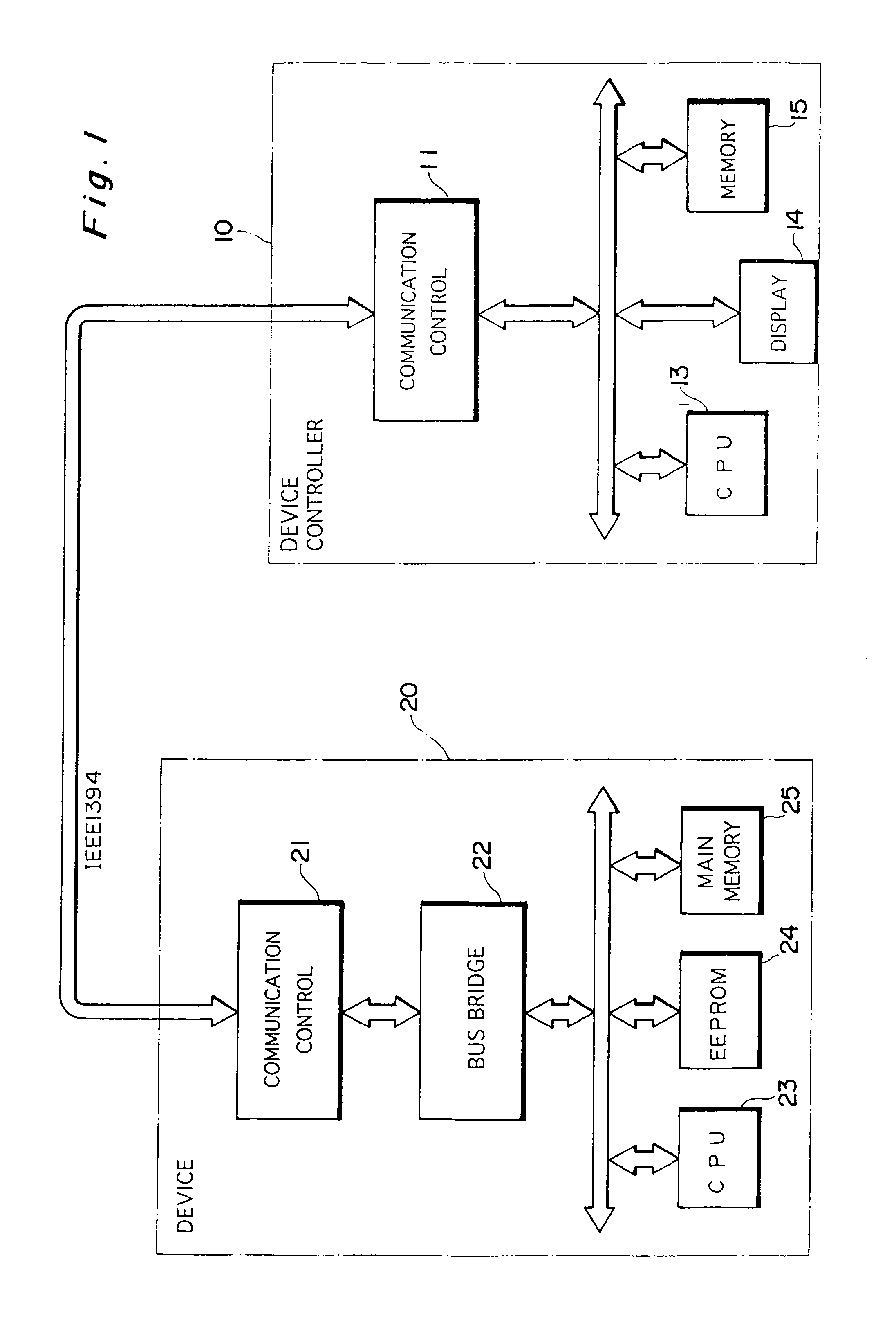
[0052]FIG. 1 is a block diagram illustrating the electrical configuration of a communication system according to a first embodiment of the present invention.

[0053]In this communication system, a device 20 (a printer or digital video camera, etc.) and a device controller 10 for controlling the device 20 are connected by a cable in accordance with IEEE 1394.

[0054]The device controller 10 has its overall operation supervised by a CPU 13. The device controller 10 includes a communication control circuit 11 for performing a data transfer in accordance with IEEE 1394, a display unit 14 whose display is controlled by the CPU 13, and a memory 15 for storing an operation program and other necessary data.

[0055]The device 20 has its overall operation supervised by a CPU 23.

[0056]The device 20 includes a communication control circuit 21 in such a manner that data transf...

second embodiment

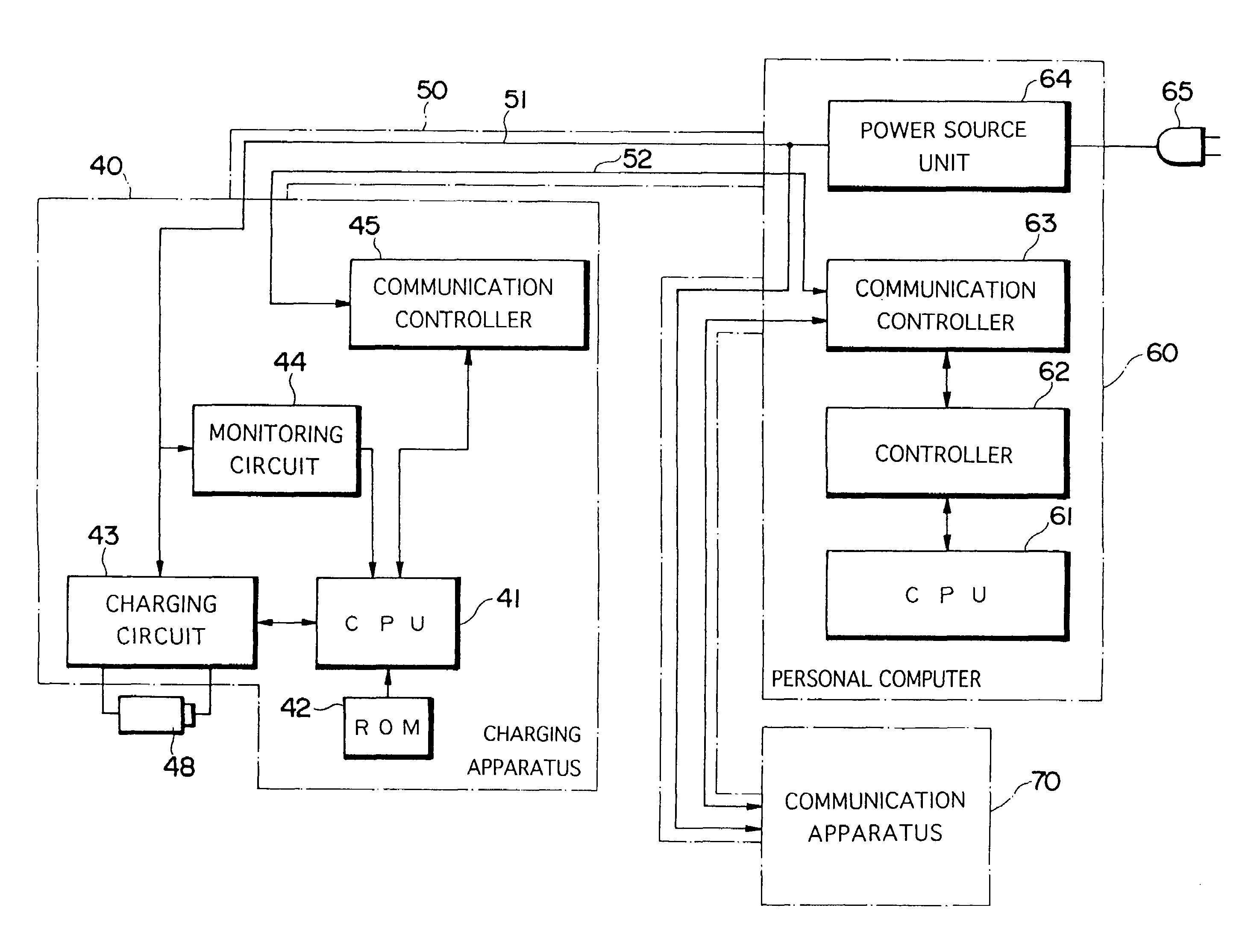
(2) Second Embodiment

[0075]FIG. 8 illustrates a second embodiment of the present invention.

[0076]As shown in FIG. 8, a charging apparatus 40, a personal computer 60 and a communication apparatus 70 are interconnected by a cable 50 in accordance with IEEE 1394. The cable 50 includes a signal line 52 for transmitting data and a power supply line 51 for supplying electric power. The cable 50 includes a ground line as well, though this is not shown. Though there are four signal lines in actuality, here only one is shown in order to simplify the drawing.

[0077]The overall operation of the charging apparatus 40 is supervised by a CPU 41. A ROM 42 storing data to be sent to and received from the personal computer 60 is connected to the CPU 41. A communication control circuit 45, which is for sending and receiving data in accordance with IEEE 1394, is also connected to the CPU 41. The communication control circuit 45 is connected to the signal line 52.

[0078]The charging apparatus 40 includes...


PUM


Abstract

A battery is charged utilizing electric power provided by a power supply line included in a cable that is in accordance with IEEE 1394. A charging apparatus and a personal computer are connected together by the cable. A power source unit in the personal computer converts AC voltage to direct voltage and supplies the DC voltage to the power supply line. The voltage is applied to a charging circuit via the power supply line, thereby charging the battery. A signal line included in the cable is used when the charging apparatus and personal computer send and receive data to and from each other.

Description

[0001]This application is a divisional of application Ser. No. 09 / 589,278, filed on Jun. 8, 2000 now U.S. Pat. No. 6,298,395, which is a divisional of application Ser. No. 09 / 014,383, filed on Jan. 27, 1998 now U.S. Pat. No. 6,138,178, the entire contents of which are hereby incorporated by reference and for which priority is claimed under 35 U.S.C. § 120; and this application claims priority of Application No. 9-28290 and 9-82421 filed in JAPAN on Jan. 27, 1997 and Mar. 17, 1997 under 35 U.S.C. § 119.BACKGROUND OF THE INVENTION[0002]1. Field of the Invention[0003]This invention relates to a data communication system and method through which a controller and a controlled device controlled by the controller perform data communication via a communication channel, and to the controller and controlled device that construct this data communication system. The invention relates further to a digital video camera and printer. The invention relates further to a method of controlling the stor...

Claims


Application Information

Patent Timeline
IPC IPC(8): G06F1/26G06F9/445G06F13/10H02J7/00H04L12/40H04L12/64
CPCG06F9/4415H04L12/40123H02J7/0052G06F13/102H02J7/00
Inventor WATANABE, MIKIOKURASE, HIROYUKI
Owner FUJIFILM CORP
Why Eureka
Try Eureka