Pressure sensor

a technology of pressure sensor and pressure sensor, which is applied in the field of pressure sensor, can solve the problems of easy introduction of foreign materials such as dust into the through hole, and achieve the effect of restricting foreign materials

Inactive Publication Date: 2007-04-03
DENSO CORP
View PDF11 Cites 22 Cited by
  • Summary
  • Abstract
  • Description
  • Claims
  • Application Information

AI Technical Summary

Benefits of technology

[0005]In view of the above-described problems, it is an object of the present invention to effectively restrict foreign materials from being introduced into a pressure sensor having a through hole through which pressure is introduced to a diaphragm to detect the pressure.
[0006]It is another object of the present invention to accurately detect pressure while it can effectively restrict foreign materials from being introduced into a pressure sensor through a through hole.
[0008]In the pressure sensor, the pedestal member has a through hole through which pressure is introduced. The through hole penetrates through from an opening of the other surface to the one surface of the pedestal member, and the through hole has a hole diameter that becomes smaller from the one surface toward the other surface of the pedestal member. Accordingly, it can effectively restrict foreign materials from being introduced into the through hole while pressure can be sufficiently introduced to the diaphragm through the through hole.

Problems solved by technology

However, in this pressure sensor, if the through hole of the glass pedestal is large, foreign materials such as dust are easily introduced into the through hole due to the pressure.

Method used


Image

  • Pressure sensor
  • Pressure sensor
  • Pressure sensor

Examples


Embodiment Construction

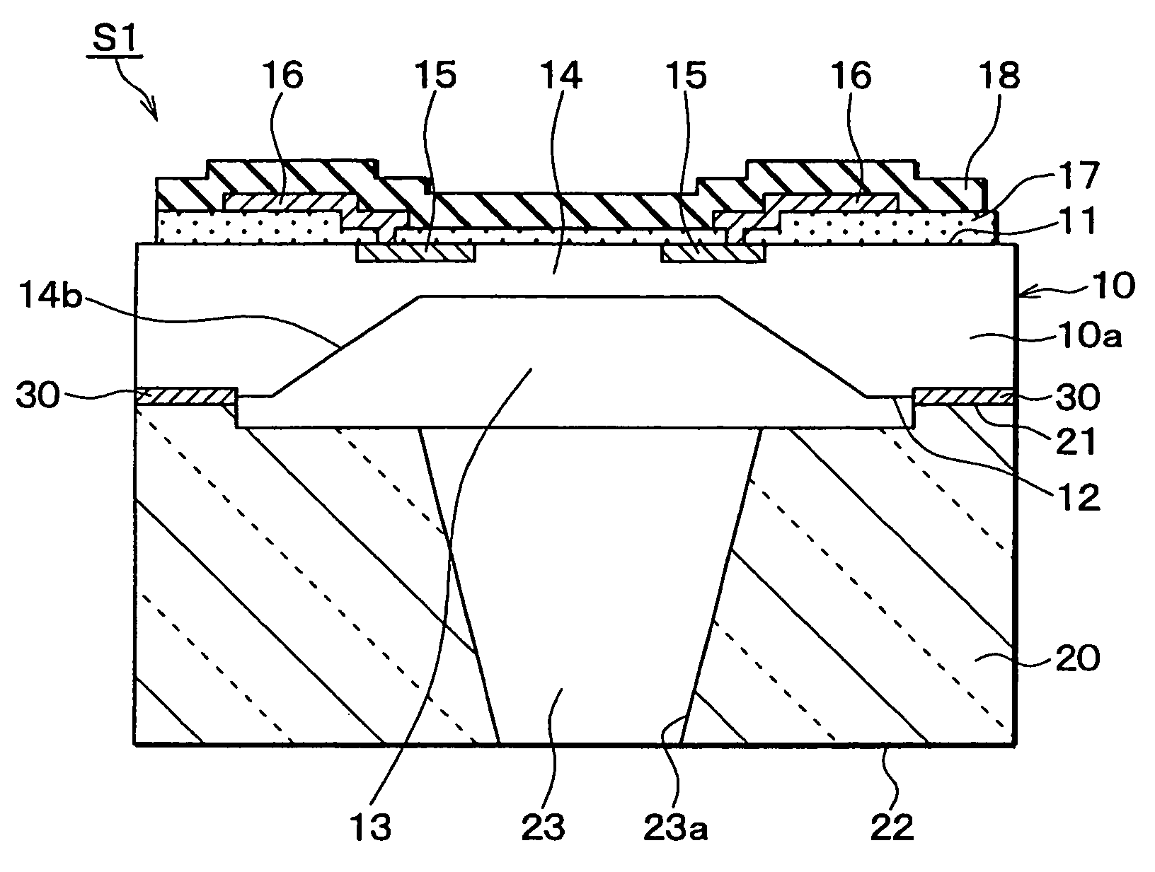
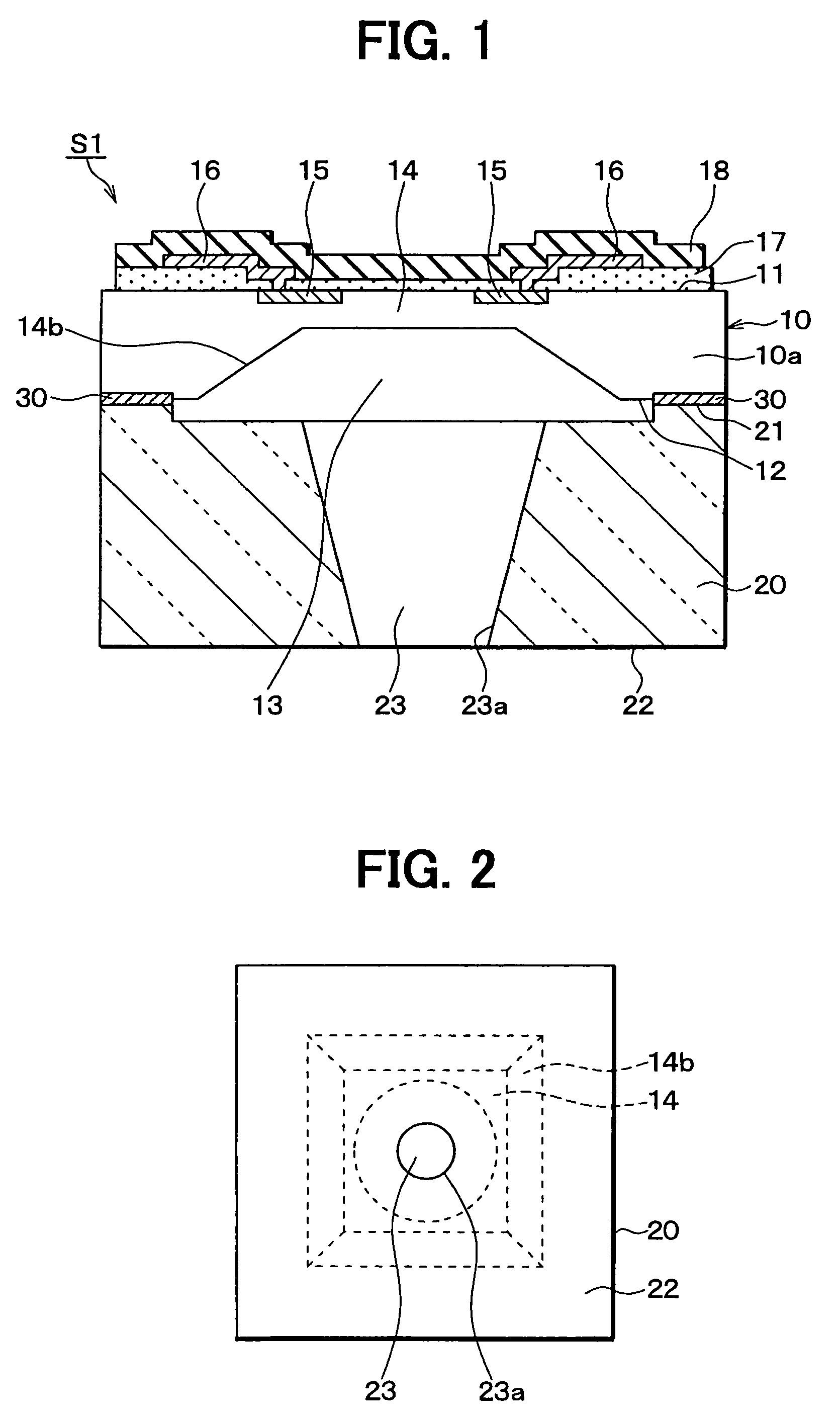
[0018]A preferred embodiment of the present invention will be now described with reference to FIGS. 1 and 2. In this embodiment, a semiconductor pressure sensor S1 is manufactured by using a silicon substrate 10 as a semiconductor substrate. The silicon substrate 10 has a first surface 11 (top surface in FIG. 1) and a second surface 12 opposite to the first surface 11. The silicon substrate 10 is formed into a rectangular plan shape in which a plan direction of the first or second surface 11, 12 is a surface (110) or a surface (100).

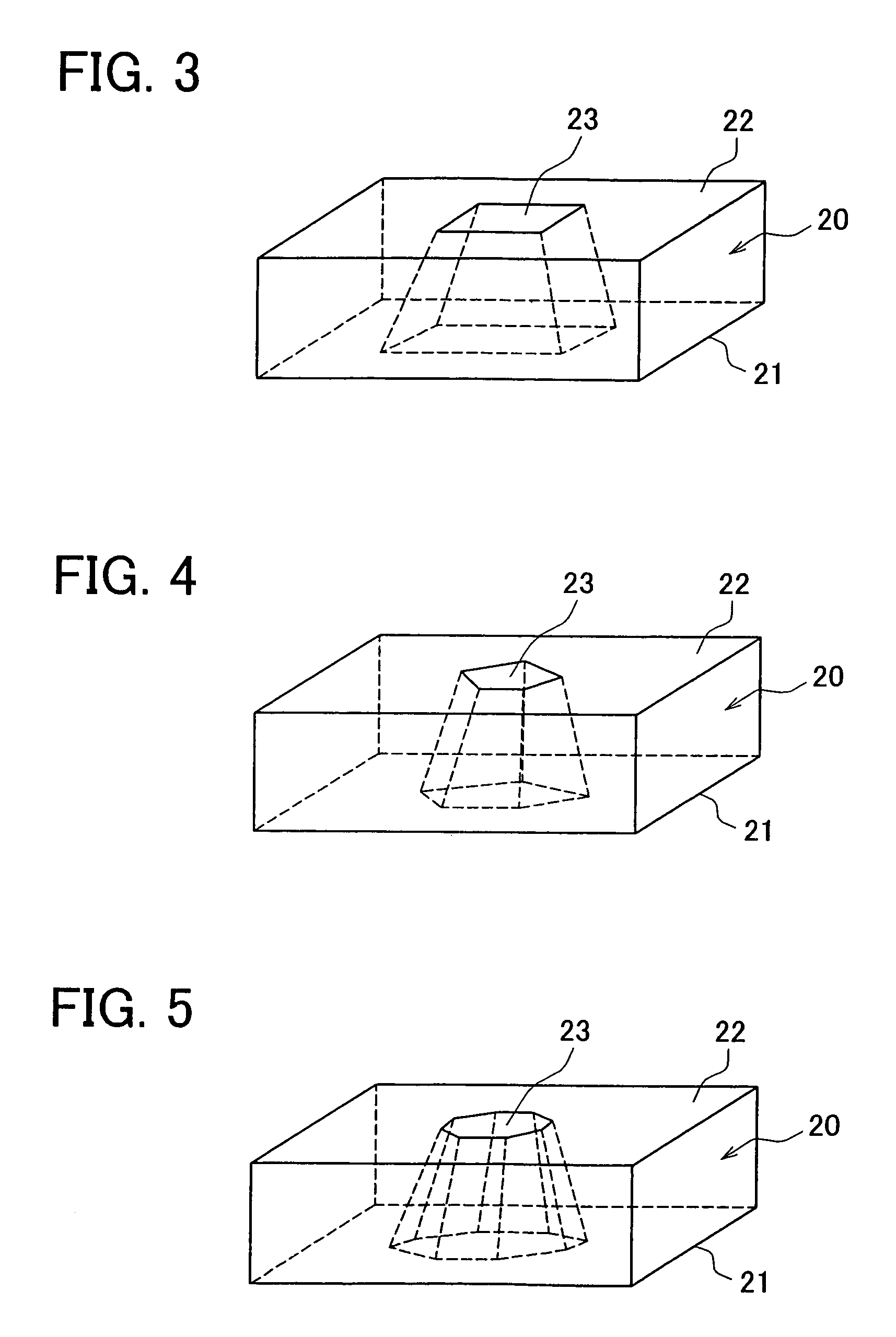
[0019]The second surface 12 of the silicon substrate 10 is recessed by anisotropic etching using an alkalis liquid, so as to form a recess portion 13. A wall thickness of the silicon substrate 10 is thinned due to the formation of the recess portion 13, and the thinned portion is used as a diaphragm 14 for detecting a pressure in the silicon substrate 10. As shown in FIG. 2, the diaphragm 14 has a square planar shape with a taper portion 14b. However, th...


PUM

PropertyMeasurementUnit
thicknessaaaaaaaaaa
thickaaaaaaaaaa
pressureaaaaaaaaaa

Abstract

A pressure sensor includes a semiconductor substrate and a pedestal member such as a glass pedestal. The semiconductor substrate has a diaphragm for detecting a pressure and a thick portion positioned around the diaphragm. The pedestal member has one surface bonded to the thick portion of the semiconductor substrate and the other surface opposite to the one surface. In the pressure sensor, the pedestal member has a through hole through which pressure is introduced to the diaphragm. The through hole penetrates through the pedestal member from an opening of the other surface to the one surface of the pedestal member, and the through hole has a hole diameter that becomes smaller from the one surface toward the other surface of the pedestal member. Accordingly, it can effectively restrict foreign materials such as dusts from being introduced into the through hole of the pressure sensor.

Description

CROSS REFERENCE TO RELATED APPLICATION[0001]This application is based on Japanese Patent Application No. 2004-31687 filed on Feb. 9, 2004, the contents of which are incorporated herein by reference.FIELD OF THE INVENTION[0002]The present invention relates to a pressure sensor, which is formed by bonding a semiconductor substrate having a diaphragm for a pressure detection to a glass pedestal having a pressure introduction hole.BACKGROUND OF THE INVENTION[0003]A pressure sensor including a semiconductor substrate and a glass pedestal is described in JP-A-2-69630 or JP-A-4-114478, for example. The semiconductor substrate includes a thin diaphragm for detecting a pressure, and a thick wall portion around the diaphragm. One side surface of the glass pedestal is bonded to the thick wall portion of the semiconductor substrate. Furthermore, a through hole is provided in the glass pedestal to penetrate through from the one side surface of the glass pedestal to the other side surface thereof...

Claims


Application Information

Patent Timeline
Patent Type & Authority Patents(United States)
IPC IPC(8): G01L21/12G01L9/00G01L9/06G01L19/00G01L19/06H01L29/84
CPCG01L9/0054G01L19/0627G01L19/0636
Inventor SAKAI, MINEKAZUSUZUKI, YASUTOSHI
Owner DENSO CORP
Why Eureka
Try Eureka