Ink jet recording apparatus

Active Publication Date: 2007-04-03
BROTHER KOGYO KK
View PDF25 Cites 12 Cited by
  • Summary
  • Abstract
  • Description
  • Claims
  • Application Information

AI Technical Summary

Benefits of technology

[0013]It is desirable that a method or configuration that thoroughly removes cleaning fluid after cleaning operations so the ink jet head will not be blocked by the remaining cleaning fluid during recording operations.
[0016]In the configuration shown in Japanese Patent Application Publication No. H10-315503, the open end of the return path from the ink jet head to the air buffer is slanted, so that reverse flow of bubbles back to the ink jet head is prevented. However, this configuration does not prevent bubbles from accumulating in the corner due to flow from the ink introduction port in the opposite direction to the outflow port as described above, and does not prevent bubbles from being drawn into the ink jet head by the operation of the suction purge in the ink jet head.
[0019]It is desirable that a head unit with the buffer tank filled with preservation fluid be capable of, when the ink jet recording apparatus is used for the first time, introducing the preservation fluid into the ink jet head and then ink with a smooth transition.
[0022]It is desirable that bubbles be prevented from clinging to the filter so that ink could effectively flow from the buffer tank to the ink jet head and that plasma processing of the filters can be carried out on the inside of the filter with certainty.

Problems solved by technology

Furthermore, this remaining cleaning fluid would flow into the manifold or the ink jet head due to vibrations during transport, and would create bubbles or form a film within the narrow flow channels.
Subsequently, the bubbles or film of cleaning fluid would block the ink channel of the ink jet head when the ink jet head was newly filled with ink to start recording operations, and this would result in a loss of a “dot”.

Method used


Image

  • Ink jet recording apparatus
  • Ink jet recording apparatus
  • Ink jet recording apparatus

Examples


Embodiment Construction

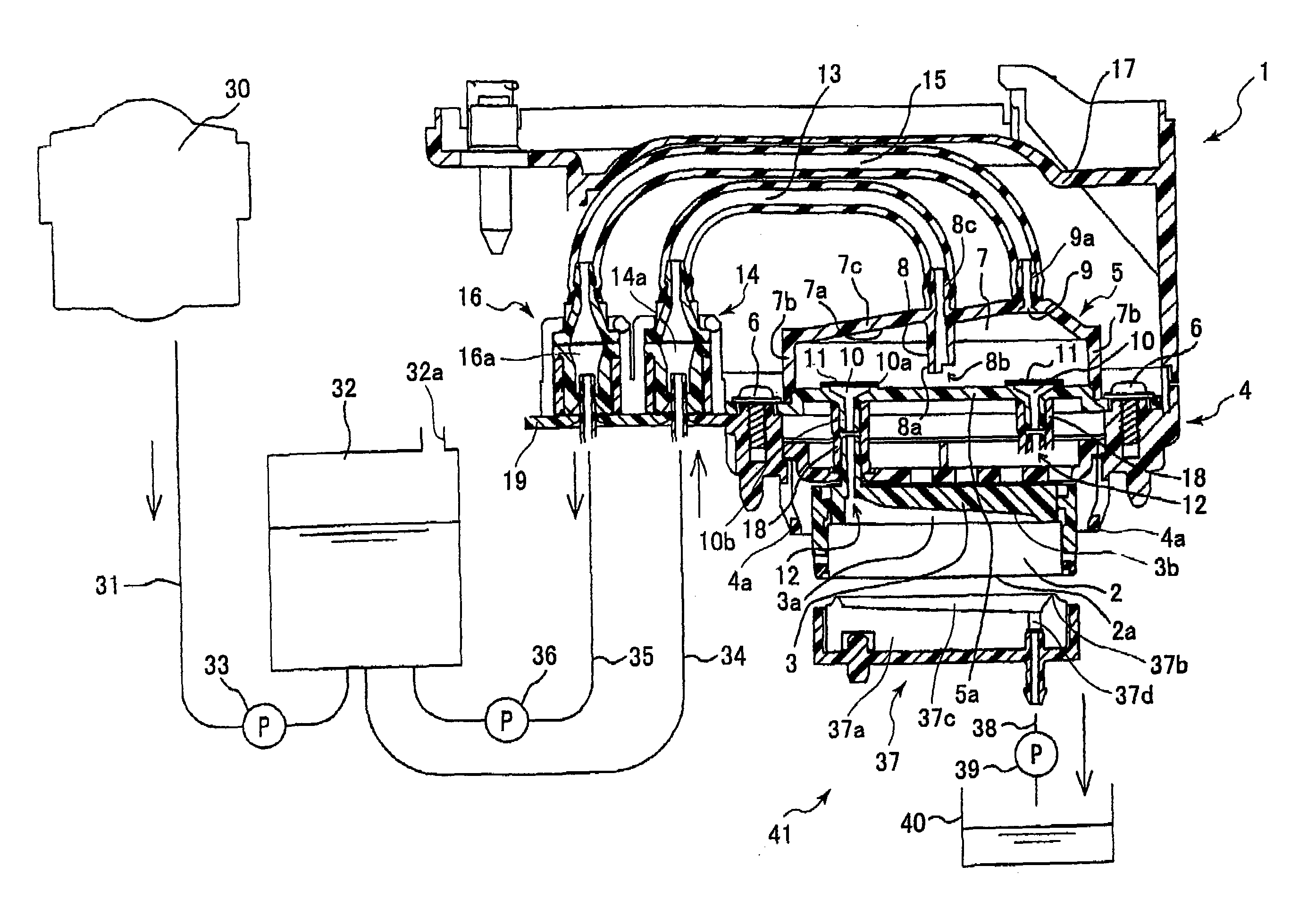
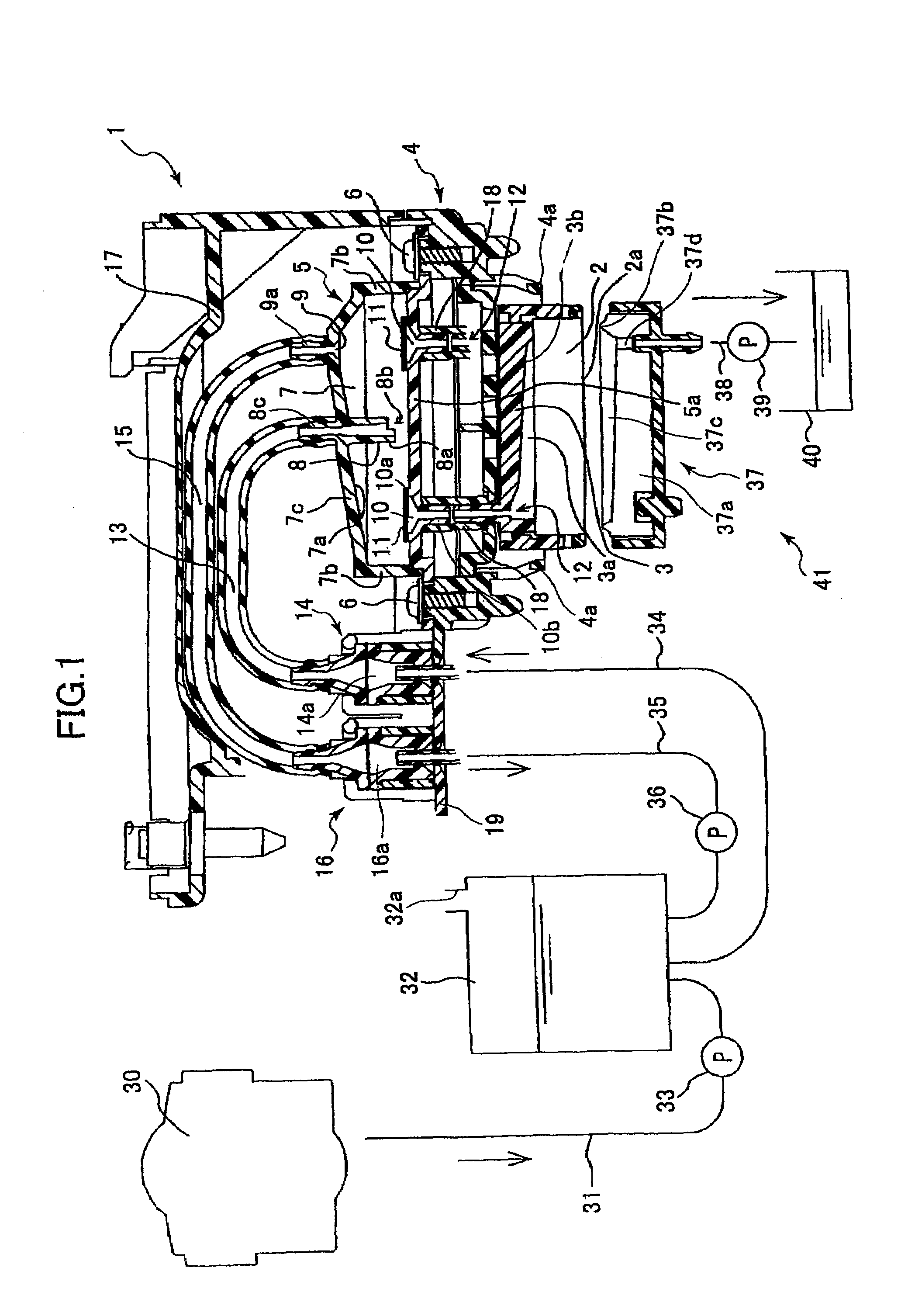
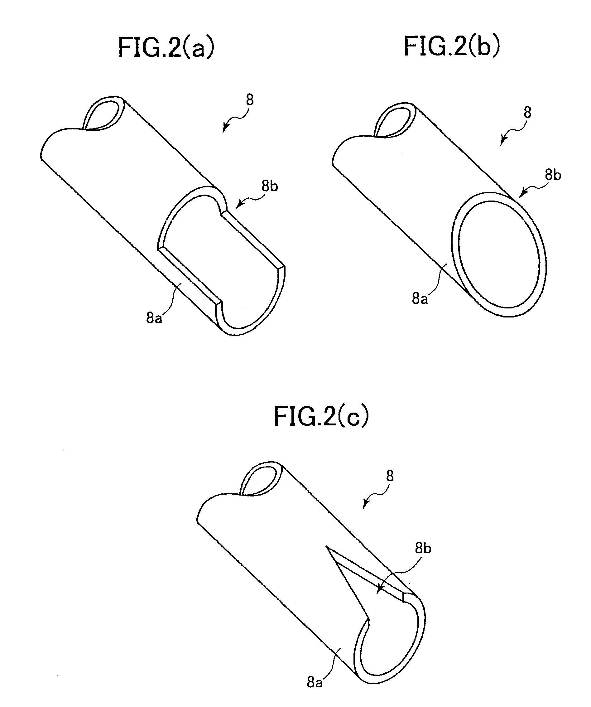
[0044]An ink jet recording apparatus according to a preferred embodiment of the present invention will be described with reference to the accompanying drawings. Firstly, the configuration of ink paths in an ink jet recording apparatus that is a preferred embodiment of the present invention will be described with reference to FIGS. 1 and 2(a). FIG. 1 is a schematic diagram of the ink paths in the ink jet recording apparatus. FIG. 2(a) is a perspective view of the end of an ink introduction port 8.

[0045]As shown in FIG. 1, a head unit 1 that can be inserted into and removed from the ink jet recording apparatus includes an ink jet head 2, a manifold 3, a buffer tank 5, tubes 13 and 15, and connectors 14 and 16. The ink jet head 2, the manifold 3, and the buffer tank 5 are fixedly mounted on a head holder 4 by screws 6. Also, the connectors 14, 16 are provided on a base extending horizontally from the head holder 4. The upper parts of connectors 14, 16 are connected to the upper part of...


PUM


Abstract

A head unit is inverted so that an outflow port is in the lowest position. Because the top wall of the buffer tank slopes downwards towards the outflow port, all remaining cleaning fluid that was introduced during manufacture is removed. Also, a notch is provided in the bottom end of an ink introduction port. The notch faces towards the outflow port so that bubbles in the ink exit from the notch and are guided towards the outflow port. The head unit is shipped while the buffer tank is filled with preservation fluid that has high wettability and any openings to the outside air are closed off with covers. When the head unit is used, the preservation fluid is sucked by a purging device and then ink, which has a high affinity for the preservation fluid, is smoothly introduced. Also, the inner surface of the filters are treated to increase the wettability by ink after the filters are fixed to the bottom lid. Afterwards the bottom lid is fixed to the top lid to form the buffer tank.

Description

BACKGROUND OF THE INVENTION[0001]1. Field of the Invention[0002]The present invention relates to an ink jet recording apparatus. In detail, the ink jet recording apparatus comprises a buffer tank, a mechanism for removing bubbles, and a head unit. The buffer tank contains ink to be supplied to the ink jet head. The mechanism for removing bubbles removes bubbles mixed into the ink, and is located between the buffer tank and the ink supply source.[0003]2. Description of Related Art[0004]Ink jet recording apparatuses that eject ink onto a recording medium based upon input signals have been known and extensively used in the art. One type is an ink jet recording apparatus in which ink from the ink source is delivered to an ink jet head through a buffer tank. The ink is directed to a plurality of ink channels in the ink jet head, and ink is ejected from nozzles in the tip of the ink channels by activation of an actuator such as a heat-generating device or a piezoelectric device. For examp...

Claims


Application Information

Patent Timeline
IPC IPC(8): B41J2/165B41J2/175B41J2/17B41J2/18B41J2/19
CPCB41J2/1707B41J2/17509B41J2/17513B41J2/17523B41J2/18B41J2/19
Inventor WANG, BINGNAKAMURA, HIROTAKEARAKAWA, MASAYUKI
Owner BROTHER KOGYO KK
Why Eureka
Try Eureka