Curved flexible light control grids with rigid framework

a flexible light control and rigid framework technology, applied in the field of curved dividers, can solve the problems of difficult transportation to the site and installation, inflexible and heavy, difficult storage and use, etc., and achieve the effect of convenient installation and high functionality

Inactive Publication Date: 2007-04-03
PILBY STEPHEN E
View PDF14 Cites 22 Cited by
  • Summary
  • Abstract
  • Description
  • Claims
  • Application Information

AI Technical Summary

Benefits of technology

[0010]The rigid framework is typically configured to accept multiple grids to create an assembly of light control grids. Preferably there are connecters to attach together the framework of light control grids, the connectors also having means to attach the assembly to structure of the building, e.g. hung by a plurality of wires. The resulting curved ceilings and walls that diffuse light while dividing a room are aesthetically pleasing and highly functional, and easy to install and inexpensive. The fasteners being moveable along the frames allows portions of the installed grids to be collapsed to gain convenient access for maintenance behind the grids as desired.

Problems solved by technology

Previously photographers utilized rigid grids or honeycombs to guide light that were difficult to store and use, and expensive.
Such grids were generally fabricated of traditional materials (e.g. wood or plastic) and were inflexible and heavy.
This made transportation to the site and installation difficult, and thus use of such grids was limited.
Although Applicant's installation at the University of South Carolina received critical acclaim, that process was awkward and labor intensive indicating that further work needed to be done developing the Lighttex™ product.

Method used


Image

  • Curved flexible light control grids with rigid framework
  • Curved flexible light control grids with rigid framework
  • Curved flexible light control grids with rigid framework

Examples


Embodiment Construction

)

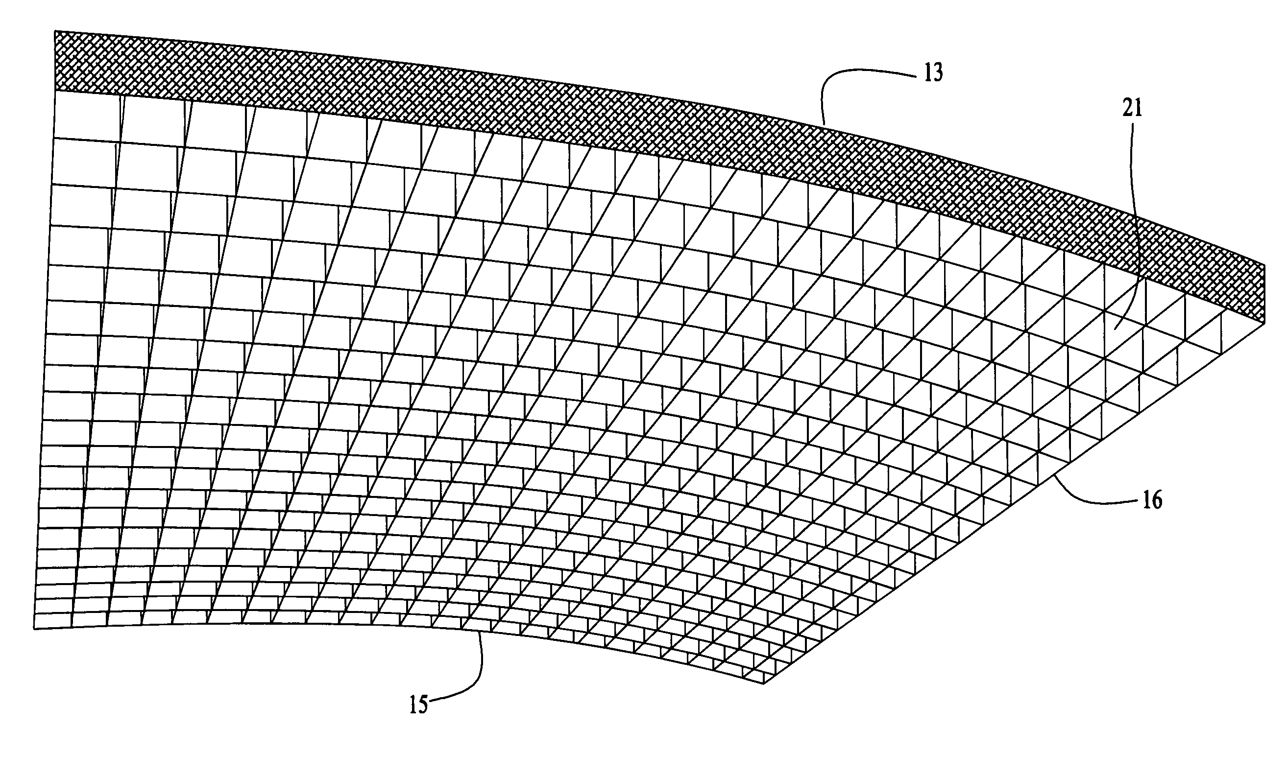
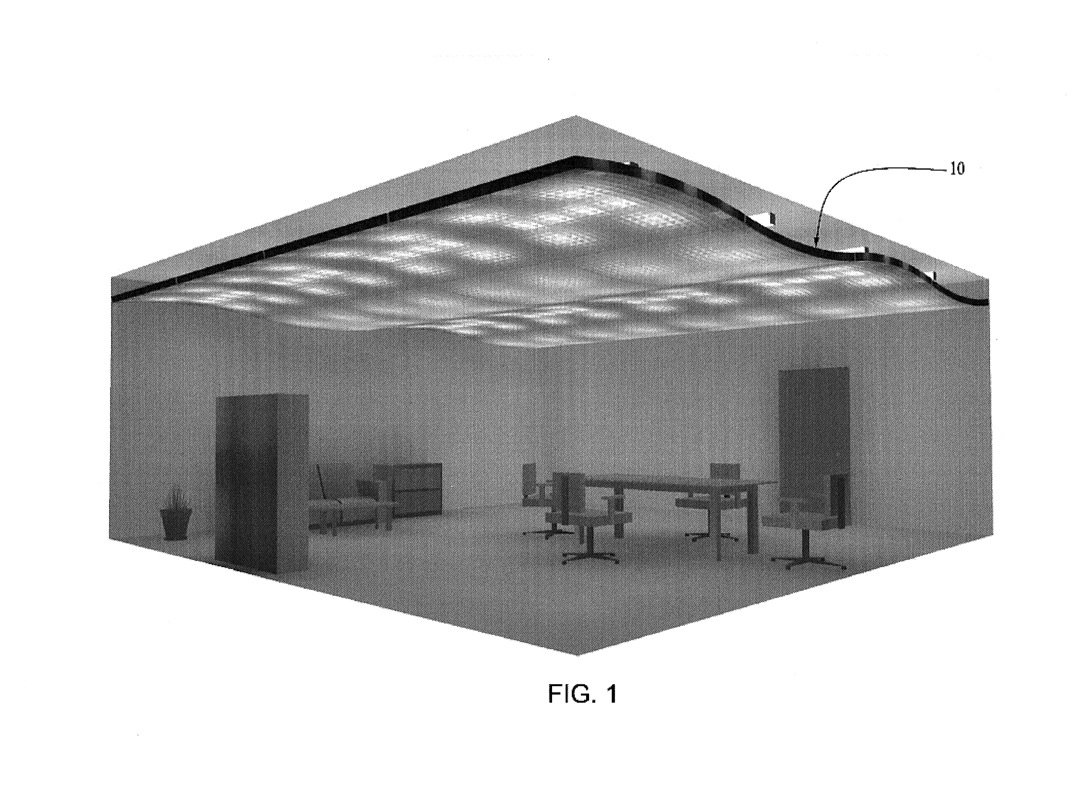
[0024]Referring to FIG. 1, shown is a curved ceiling assembly 10 of the preferred embodiment of the present invention. The curved ceiling 10 is constructed of a number of light control grids 13 assembled together and suspended from the structure of the building. The curved ceiling 10 is aesthetically pleasing in obscuring in part the upper portion of the room and functional in diffusing the light from the light fixtures.

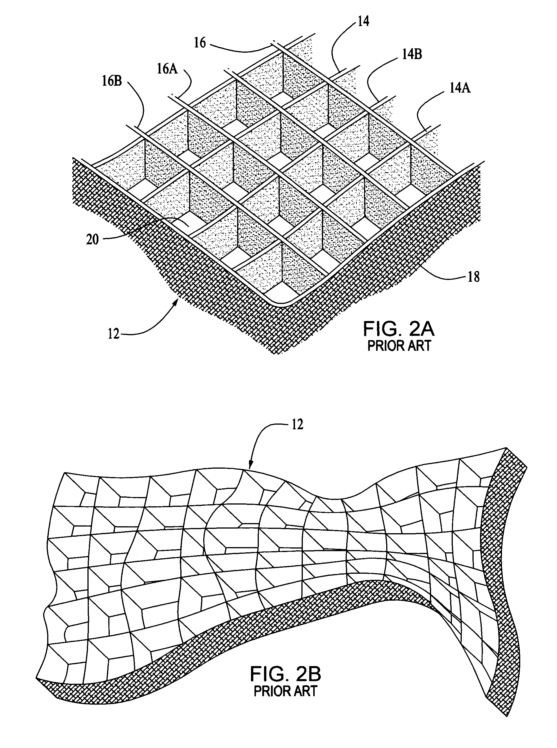
[0025]FIGS. 2(a), (b) show a portion of the light control grid 12 and its collapsibility from the prior Pilby U.S. Pat. No. 5,556,186. The light control grid 12 is formed from a plurality of flexible, fabric strips 14, 16 bounded on the perimeter of the grid by a flexible strip 18. The fabric strips 14, 16 form connected open ended laterally bound light channels 20. Reflecting material may be placed on inside facing edges 14a, 14b, 16a, 16b of strips 14. 16 to guide light from the light source(s) or depending upon the lighting objectives for the area. Referring to F...


PUM


Abstract

Light control grids in curved ceilings or walls include an assembly of flexible, spaced-apart sets of fabric strips that intersect and interlock, one of the sets of strips being substantially curved along its length and / or of varying length. The grids are supported by a modular rigid framework that maintains the strips taut, the frames being substantially curved corresponding to the curved strips and / or strips of varying length. A number of connectors hold the frames together and are used to attach the assembly to the building, and a number of releasable fasteners moveably retained by the frames attach the grids to the frames.

Description

BACKGROUND OF THE INVENTION[0001]1. Background of the Invention[0002]This invention relates to curved dividers that diffuse light for buildings.[0003]2. Description of the Related Art[0004]Applicant's Lighttools® Soft Egg Crates® light control grids as described in Pilby U.S. Pat. No. 5,556,186 have become standard equipment in the film production industry for blocking and shaping soft light, i.e., maintaining desirable large light source characteristics while at the same time controlling extraneous spread of side light. These light control grids are fabricated from intersecting and interlocking strips of fabric slotted in a complimentary manner, the resulting assembly completely collapsible to fit into a lightweight package about the size of a shoe box. Previously photographers utilized rigid grids or honeycombs to guide light that were difficult to store and use, and expensive.[0005]A similar situation existed in the field of light control for open spaces such as inside commercial...

Claims


Application Information

Patent Timeline
Patent Type & Authority Patents(United States)
IPC IPC(8): F21V11/06E04C2/42E04B9/00E04B9/32E04B9/34G03B15/02
CPCE04B9/00E04B9/32E04B9/345
Inventor PILBY, STEPHEN E.
Owner PILBY STEPHEN E
Why Eureka
Try Eureka