Method of operating a safety system for airports and airfields

a safety system and airport technology, applied in landing aids, instruments, roads, etc., can solve the problems of the greatest potential danger of aircraft, achieve the effect of reducing the risk of aircraft collision, improving the safety of airport vehicles, and slowing down the movement of aircra

Inactive Publication Date: 2007-04-03
ACT GLOBAL HLDG LLC
View PDF57 Cites 18 Cited by
  • Summary
  • Abstract
  • Description
  • Claims
  • Application Information

AI Technical Summary

Benefits of technology

[0040]It is therefore an advantage of the present invention to provide an artificial turf system for airports and airfields that retards birds and other animals and has a sub-surface that enhances water drainage and as well as the accessibility of airport vehicles.
[0041]Another advantage of the present invention is to provide an artificial turf system for airports and airfields that includes an artificial turf surface and a sub-surface that slows a moving aircraft.
[0042]A further advantage of the present invention is to provide an artificial turf adapted to retard or repel loitering animals.
[0043]Other objects, features and advantages of the invention will be apparent from the following detailed disclosure, taken in conjunction with the accompanying sheets of drawings, wherein like numerals refer to like parts, elements, components, steps and processes.

Problems solved by technology

The lack of natural grass, grubs, insects, rodents and other small animals virtually eliminates all food sources for birds, which provide the greatest potential danger to aircraft.

Method used


Image

  • Method of operating a safety system for airports and airfields
  • Method of operating a safety system for airports and airfields
  • Method of operating a safety system for airports and airfields

Examples


embodiment 140

[0112]The interface embodiment 140 includes digging a trench 144 into the existing soil 58 along a desired interface line of the airfield. The trench 144 is preferably sufficiently deep to secure a piece of vertical turf 146 that is folded over the base material 70 and backfilled with compacted soil 148. A one foot (30 cm) deep by four inch (10 cm) wide trench is generally sufficient. Well known trenchers can dig thousands of feet of this trench in an hour. The system implementor then plants natural grass sod 142 or seed, depending on the proximity of the interface to the runway or taxiway (sod too close to the runway can fly up and become a FOD, however, a turf / grass interface is preferably at least 150 feet (45 m) from the runway or taxiway).

Arrester Bed System

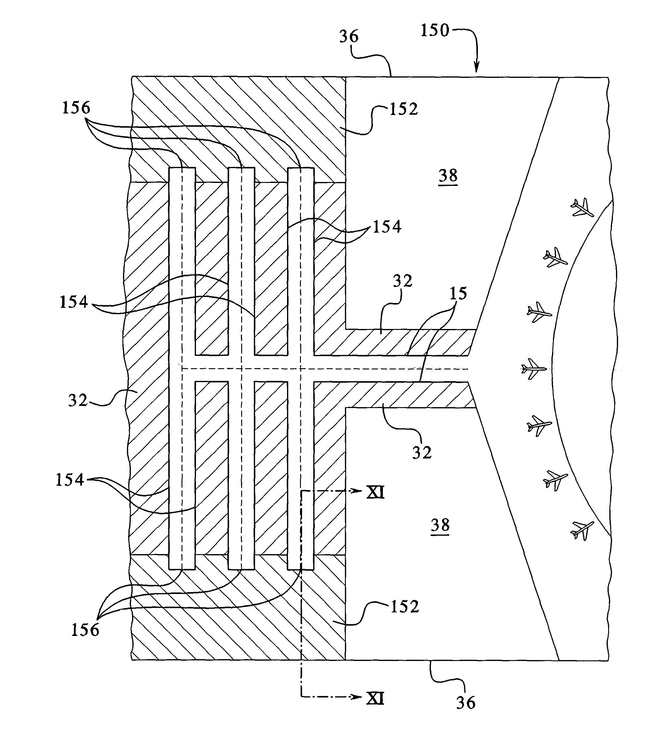
[0113]Referring now to FIG. 10, a top plan sectional view of an airport or airfield 150, including sections of airport runways, taxiways and areas 152 of adjacent synthetic turf employing a soft ground arrester system of the...

embodiment 170

[0131]Referring now to FIG. 12, a front elevation sectional view through an embodiment 170 of artificial or synthetic turf is illustrated, wherein a plurality of the grass-like fibers 90 are replaced by stiff, spiny, barbed, needle bearing or prickly fibers or any combination thereof which are referred to herein as repelling fibers 172, and which repel loitering animals. The repelling turf 170 is preferably laid over a sheet 84. As discussed above in the flow-through embodiment of FIG. 3, the sheet 84 is a weed barrier. In a sheeting embodiment discussed in FIG. 7, the sheet 84 preferably includes a waterproof membrane. A 12 or 15 foot (3.6 or 4.5 m) roll of the repelling turf 170 preferably includes a primary flexible backing 86, e.g., of double woven polypropylene and a secondary flexible backing 88, e.g., which is preferably polyurethane. The backings are alternatively any known primary or secondary backing, some of which are disclosed above in connection with FIG. 1. The thickne...


PUM


Abstract

A method for installing an aesthetically pleasing artificial turf that retards birds and other animals and a sub-surface that supports the weight of an aircraft, enhances water drainage and enables the accessibility of airport vehicles to all parts of a runway or taxiway is disclosed.

Description

PRIORITY CLAIM[0001]This application is a divisional application of U.S. patent application Ser. No. 09 / 727,276, filed on Nov. 30, 2000 now U.S. Pat. No. 6,620,482, entitled, “SAFETY SYSTEM FOR AIRPORTS AND AIRFIELDS”.DESCRIPTION[0002]The present invention relates in general to a safety system for airports and airfields, and more particularly to a synthetic turf surface and accompanying sub-surface installed substantially adjacent to airport runways and taxiways and a method for installation of said surface and said sub-surface.BACKGROUND OF THE INVENTION[0003]Airfields, including military airfields, small airfields and large commercial airports presently have grass surfaces adjacent to the airport runways and taxiways. These natural grass surfaces are difficult, time consuming and expensive to maintain and are not aesthetically pleasing. More importantly, the existing grass surfaces create potential safety problems for departing and arriving aircraft. The existing grass surfaces al...

Claims


Application Information

Patent Timeline
Patent Type & Authority Patents(United States)
IPC IPC(8): E01C21/00A01M29/32B64F1/00B64F1/18E01C9/00
CPCB64F1/00B64F1/18E01C9/00Y10T428/2443Y10T428/24595A01M29/32E01H1/001G06Q99/00B64F1/025Y10T428/23921G06Q30/0241
Inventor CARR, PATRICK J.COLLETT, DALE L.SCHOMBURG, WILLIAM L.SULLIVAN, THOMAS M
Owner ACT GLOBAL HLDG LLC
Why Eureka
Try Eureka