
Probe apparatus for use in a separable connector, and systems including same

a technology of probe apparatus and separable connector, which is applied in the direction of ac/dc measuring bridge, coupling device connection, instruments, etc., can solve the problems of energized conductor, safety hazards for personnel working on and around voltage sensing systems, and substantial limited dynamic range, bandwidth, linearity,

Active Publication Date: 2007-04-03
MICATU
View PDF25 Cites 21 Cited by
  • Summary
  • Abstract
  • Description
  • Claims
  • Application Information

AI Technical Summary

Benefits of technology

"The patent describes a probe apparatus that is used in a separable connector. This apparatus includes an insulating body and two electrical conductors that are in contact with the insulating body. The conductors have adjacent surfaces that create an electric field when an electrical potential is applied between them. The insulating body has an opening that can hold a sensor, and when the sensor is exposed to the electric field, it can measure voltage. This patent also describes a separable electrical connector system that includes this probe apparatus and a voltage sensor that can measure voltage. The technical effect of this invention is to provide a reliable and accurate way to measure voltage in a separable connector system."

Problems solved by technology

In addition to being relatively large and heavy, these devices have substantially limited dynamic range, bandwidth, linearity, and electrical isolation.
Further, during electrical fault conditions, these transformers can conduct dangerous levels of fault energy to downstream instrumentation and personnel, thus creating safety hazards for personnel working on and around the voltage sensing systems.
This direct electrical contact with an energized conductor presents a safety hazard for personnel working on and around voltage sensing systems including the sensors.

Method used


Image

  • Probe apparatus for use in a separable connector, and systems including same
  • Probe apparatus for use in a separable connector, and systems including same
  • Probe apparatus for use in a separable connector, and systems including same

Examples


Embodiment Construction

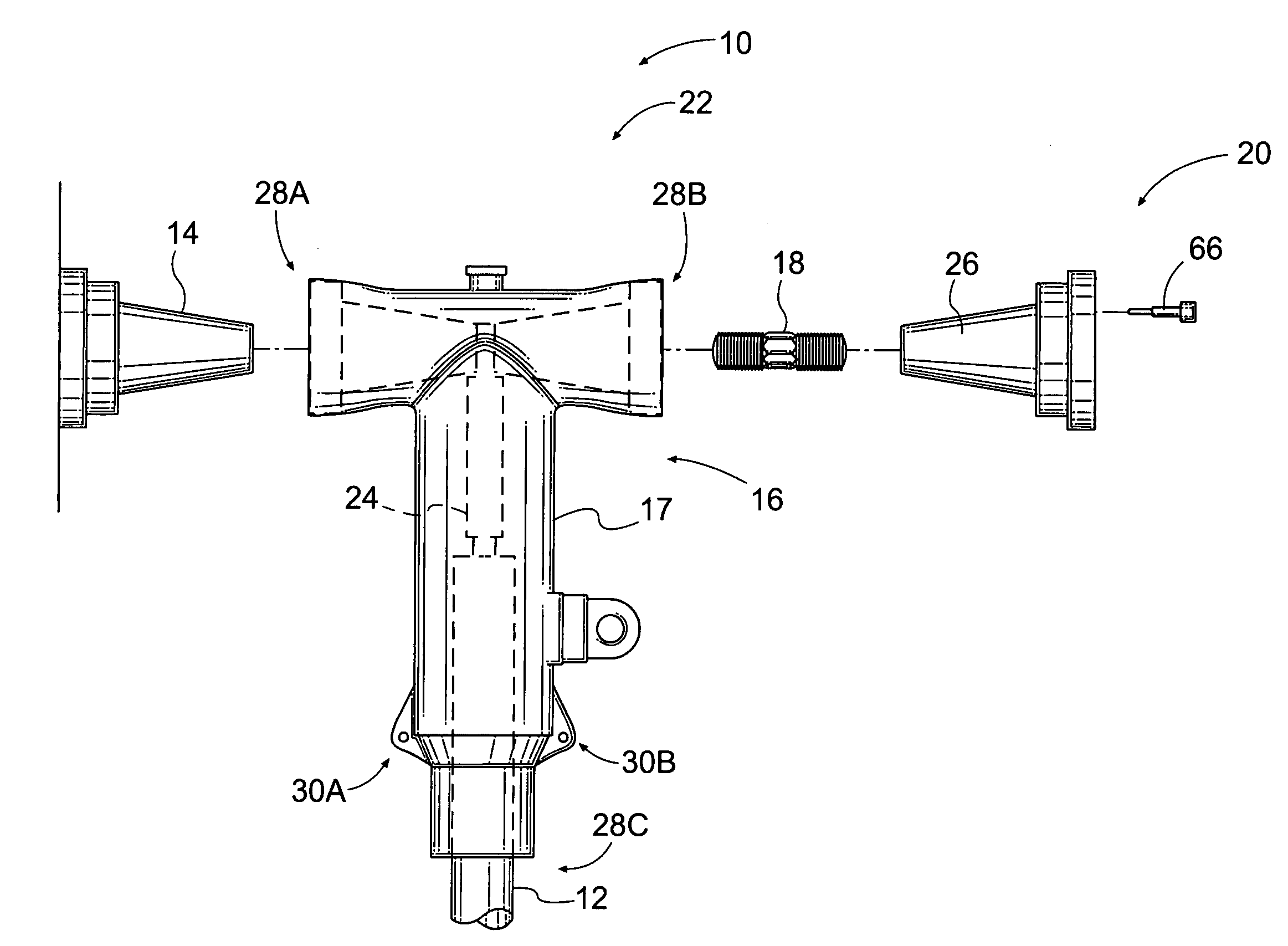
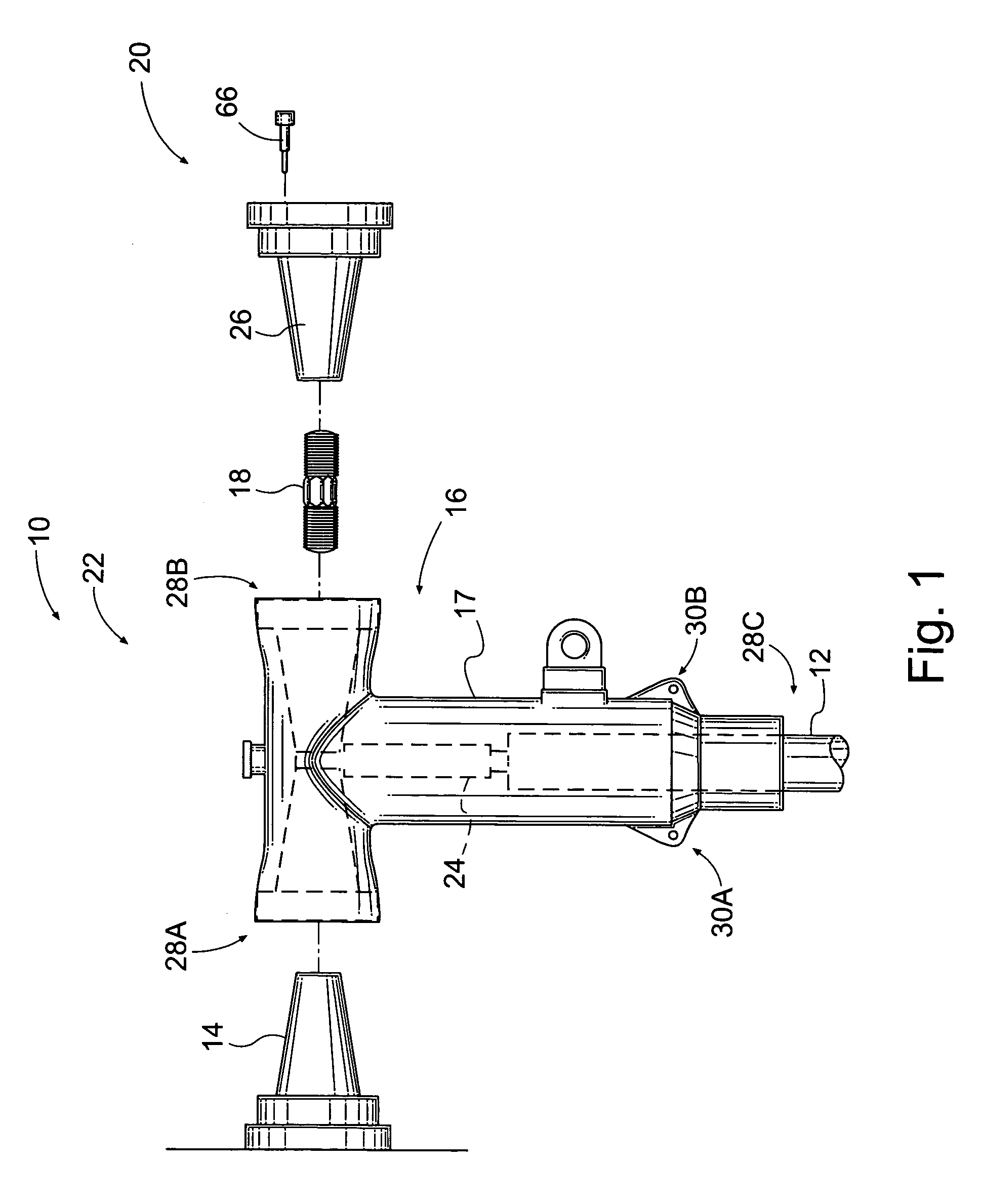
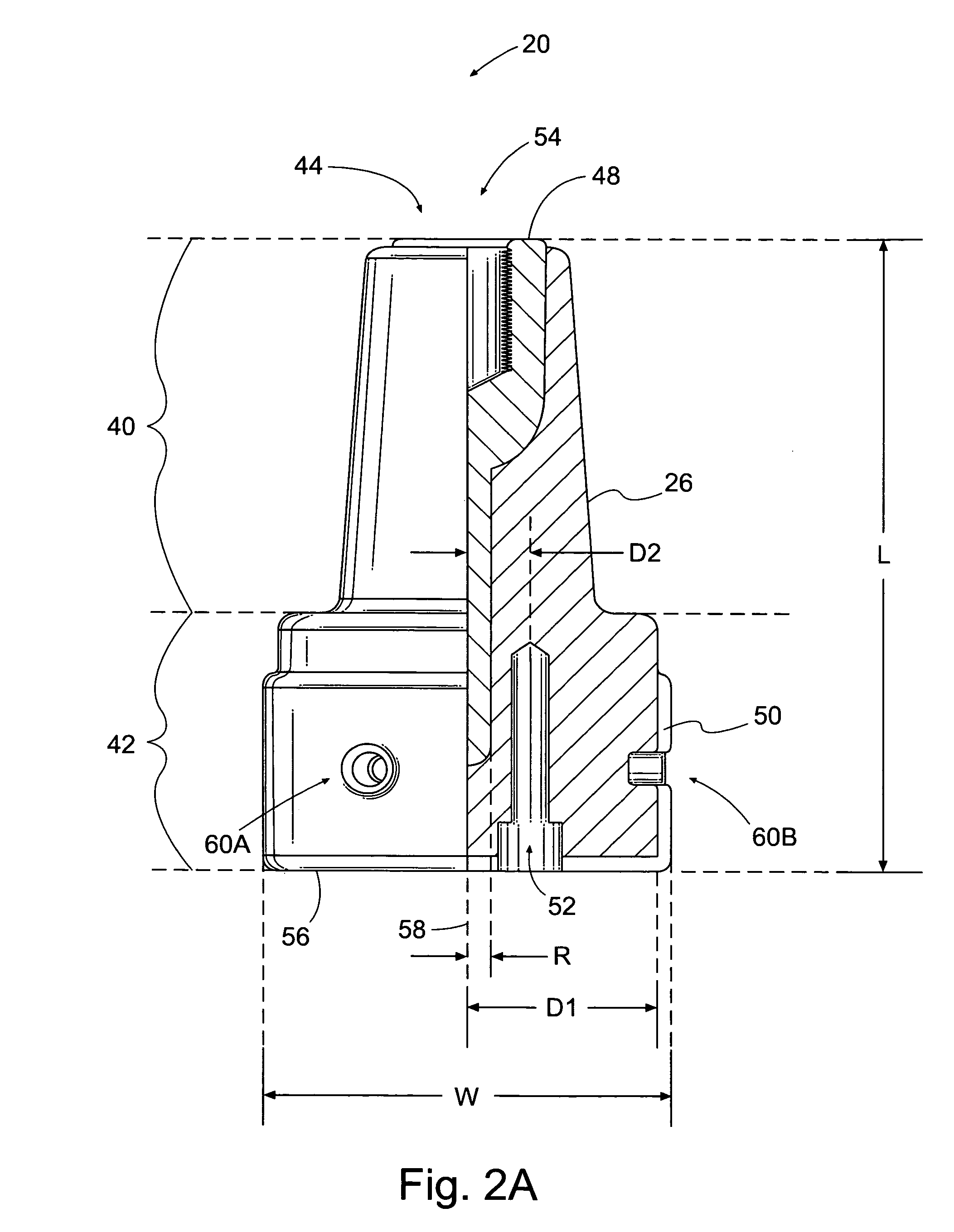
[0022]FIG. 1 is a side view of one embodiment of a separable electrical connector system 10 that includes a probe apparatus 20 of the present invention. The probe apparatus 20 includes an insulating body 26 and a sensor 66 that is adapted to fit within the insulating body 26 to measure the voltage of a cable 12 adjacent the probe apparatus 20.

[0023]In one embodiment, the connector system 10 includes a connector (i.e., T-connector) 16, a stud 18 having opposed threaded ends, and the probe apparatus 20. In combination, the T-connector 16, the stud 18, and the probe apparatus 20 form a separable connector 22 for connecting the cable 12 to the apparatus bushing 14.

[0024]In general, the T-connector 16 has a central conductor 24 positioned within a “T”-shaped second insulating body 17. The second insulating body 17 may have a plurality of openings, in this case three openings 28A–28C. In this embodiment, openings 28A and 28B are opposed and coaxial as shown in FIG. 1; however, other arran...


PUM

PropertyMeasurementUnit
voltagesaaaaaaaaaa
electrical fieldaaaaaaaaaa
electrical potentialaaaaaaaaaa

Abstract

A probe apparatus disclosed for use in a separable connector includes an insulating body and spaced apart first and second electrical conductors in contact with the insulating body. The first and second electrical conductors have adjacent surfaces configured such that when an electrical potential is applied between the conductors, an electric field is formed between the conductors. The insulating body has an opening positioned between the conductors and adapted to receive a sensor such that a portion of the sensor is subjected to the electric field. A separable electrical connector system is described including the probe apparatus, as is a voltage sensing system including the probe apparatus and a voltage sensor positioned within the opening of the insulating body.

Description

CROSS-REFERENCE TO RELATED APPLICATIONS[0001]Not ApplicableSTATEMENT REGARDING FEDERALLY SPONSORED RESEARCH[0002]Not ApplicableBACKGROUND OF THE INVENTION[0003]1. Field of the Invention:[0004]This invention relates generally to sensor probe apparatus, and more particularly to probe apparatus for sensing voltage via an electric field.[0005]2. Description of Related Art:[0006]In electrical power generation and distribution systems, high voltages (e.g., 2,000 volts and above) are commonly measured via instrument transformers mounted on poles. In addition to being relatively large and heavy, these devices have substantially limited dynamic range, bandwidth, linearity, and electrical isolation. Further, during electrical fault conditions, these transformers can conduct dangerous levels of fault energy to downstream instrumentation and personnel, thus creating safety hazards for personnel working on and around the voltage sensing systems.[0007]In an effort to reduce or eliminate these pro...

Claims


Application Information

Patent Timeline
Patent Type & Authority Patents(United States)
IPC IPC(8): G01R19/14G01R31/04H01R9/03
CPCG01R15/16
Inventor JOHNSON, LEONARD A.HARLEV, JOSEPH YOSSIBRANNING, JR., JOHN M.ELLIOTT, ROBERT D.
Owner MICATU
Learn More