
Automatic capacitor discharge for power supplies

a technology of automatic discharge and power supply, which is applied in the direction of emergency protective circuit arrangement, power conversion system, electrical equipment, etc., can solve the problems of large residual charge at high voltage, significant hazard to service and operating personnel, and to the power supply itself and associated equipment, and achieve the effect of quick and automatic discharge of residual high voltage charg

Inactive Publication Date: 2007-04-03
LA MARCHE MFG
View PDF5 Cites 28 Cited by
  • Summary
  • Abstract
  • Description
  • Claims
  • Application Information

AI Technical Summary

Benefits of technology

[0009]Accordingly, it is an object of the present invention to avoid hazardous operating conditions in a high voltage power supply or battery charger by quickly and automatically discharging residual high voltage charge.
[0010]It is another object of the present invention to provide for the automatic, safe and rapid discharge of output filter capacitors in a power supply when the load is removed and the power supply is turned off without increasing the load during normal power supply operation.
[0011]Yet another object of the present invention is to provide for the high voltage discharge of post rectification filter capacitors in a power supply at turn-off for improved human safety and equipment protection.

Problems solved by technology

This large residual charge at high voltage poses a significant hazard to service and operating personnel, as well as to the power supply itself and associated equipment.
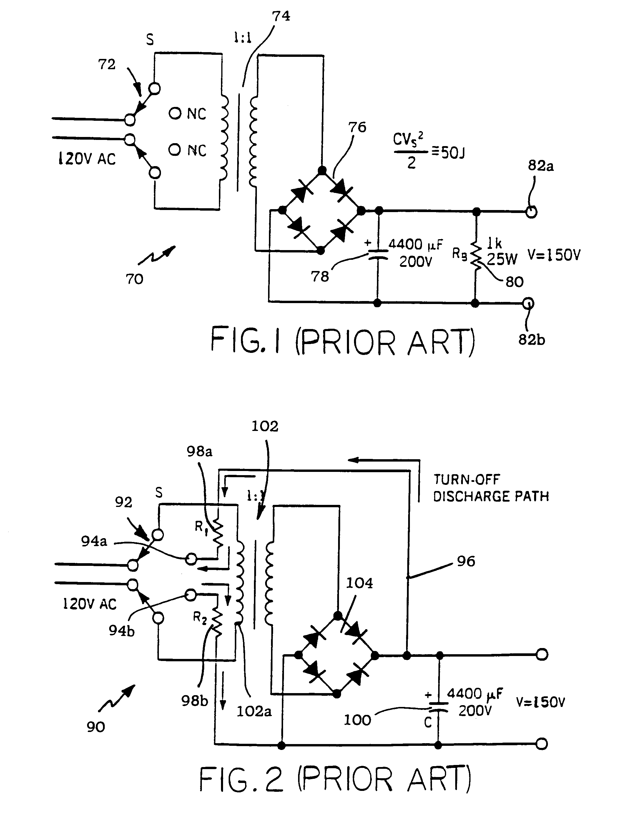
The primary problem with this approach is the presence of the bleed resistor 80 in the circuit during operation of the DC power supply 70, resulting in substantial energy dissipation via the bleed resistor.
However, this approach requires a complicated switching arrangement at the input of the DC power supply.
This latter approach is, of course, not automatic.
Other approaches are automatic in operation, but require additional circuitry in the power supply, resulting in a more complicated arrangement and require circuitry for interfacing the power supply with the energy discharge circuit.
Moreover, modern high power supply modules are hot unpluggable and therefore have no mechanical power switches.

Method used


Image

  • Automatic capacitor discharge for power supplies
  • Automatic capacitor discharge for power supplies
  • Automatic capacitor discharge for power supplies

Examples


Embodiment Construction

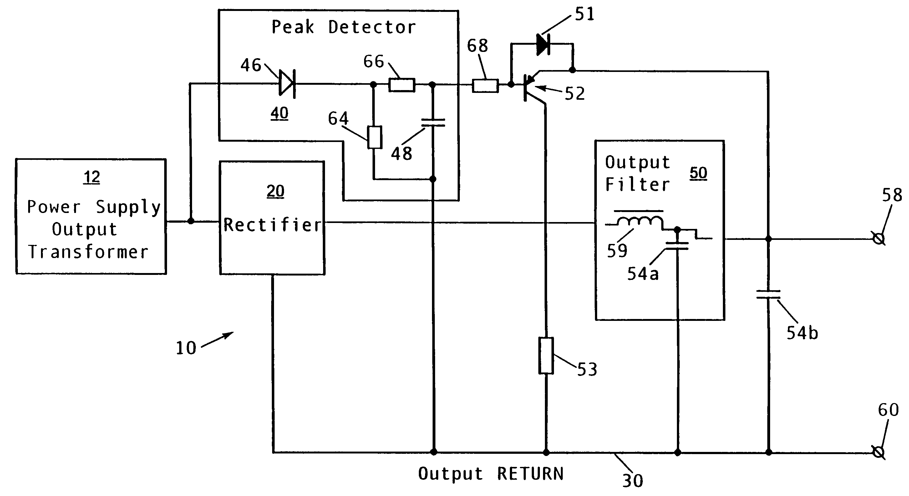
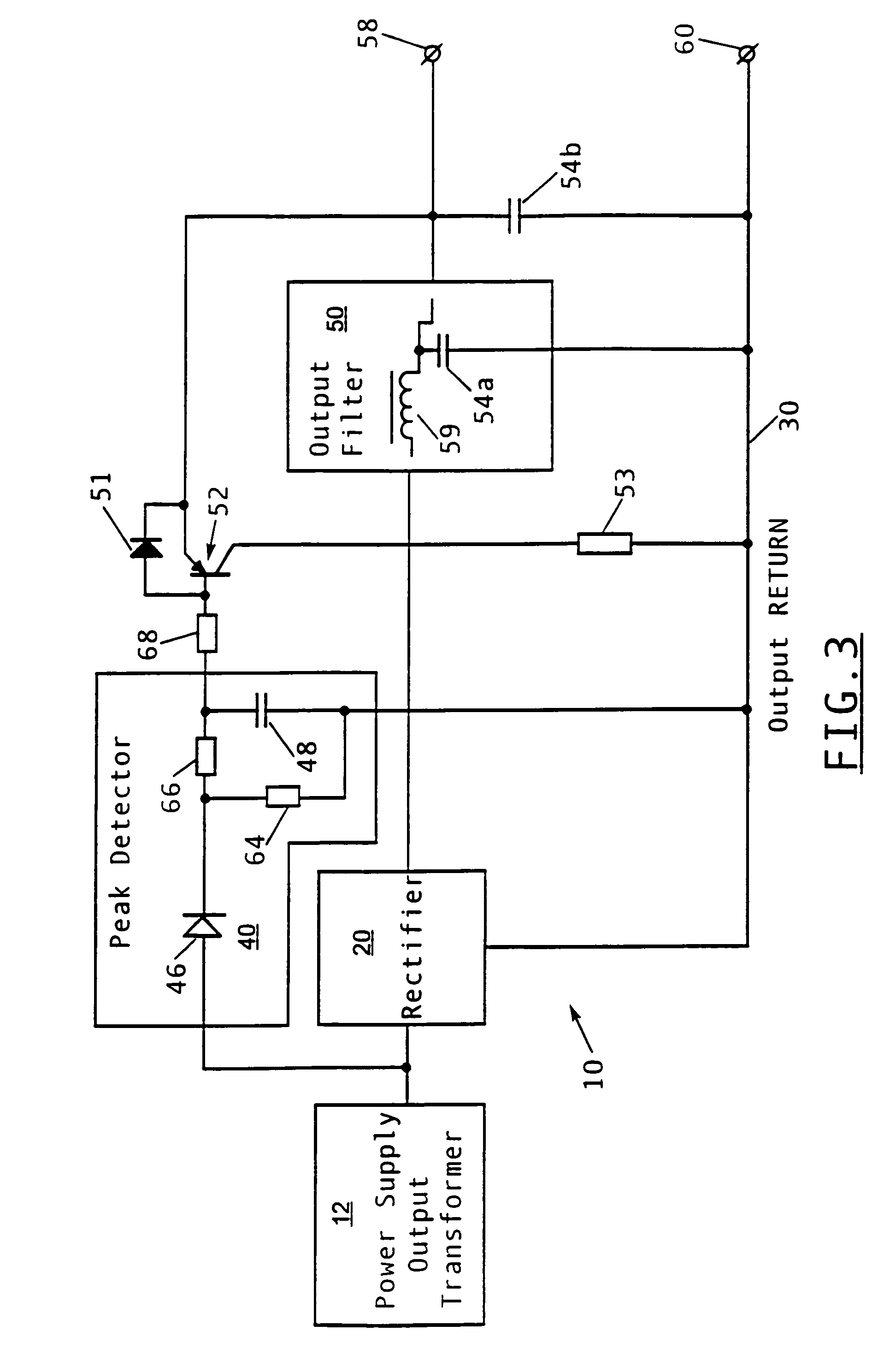
[0019]Referring to FIG. 3, there is shown a schematic diagram of a power supply 10 with automatic output filter capacitor discharge in accordance with the principles of the present invention. The inventive power supply 10 is intended for use in a DC power supply where a DC or AC input voltage is converted to a DC output voltage. These types of DC power supplies are used in various applications such as in battery chargers, telecommunications systems, motor drives, etc. However, the inventive capacitor discharge arrangement is not limited to the specific power supply arrangement disclosed herein, but is applicable to virtually any type of DC output device incorporating output filter capacitors which remain charged after the converter is turned off and the output load is removed.

[0020]Power supply 10 includes an output transformer 12 which may be either a line transformer of a linear power supply or an output transformer of a switching power supply. Power supply 10 further includes a r...


PUM


Abstract

In a DC power supply or a battery charger, plural output filter capacitors remain highly charged after the load is removed and the converter is turned off. A transistor connected across the capacitors is non-conductive during normal power supply operation and a bleed resistor connecting the transistor to the output capacitors is not in the circuit during normal power supply operation. When the power supply is turned off and the load is removed, the transistor is automatically rendered conductive with the removal of the pulsed output of the power supply's power transformer to the transistor, with the energy stored in the capacitors safely and quickly discharged to the output return via the bleed resistor which is placed in circuit by the conducting transistor.

Description

FIELD OF THE INVENTION[0001]This invention relates generally to power supplies and battery chargers and is particularly directed to an arrangement for automatically and safely discharging a high voltage charge stored in the output filter capacitors of a power supply to essentially zero potential when the load is removed or the power supply is turned off.BACKGROUND OF THE INVENTION[0002]Power supplies of various types are widely used in electronics and can be found in literally any electronic device. Many of these power supplies produce a high voltage output and are capable of driving hazardous voltages and current. Unless special provision is made, these power supplies can retain a large voltage in their output filter capacitors even when the power supply is turned off or the output load is removed. The energy stored in the output filter capacitors is given by the expression[0003]Energy=CV22,⁢whereC=the⁢⁢capacitance,⁢andV=the⁢⁢output⁢⁢voltage.[0004]This energy is typically measured ...

Claims


Application Information

Patent Timeline
IPC IPC(8): H02M1/14
CPCH02M1/36H02M2001/322H02M1/322
Inventor MIRSKIY, GREGORY
Owner LA MARCHE MFG
Learn More