
Background suppression and color adjustment method

a color adjustment and suppression method technology, applied in the field of background suppression and color adjustment methods, can solve the problems of large image data volume, large amount of storage space required for document scanning at high resolution, and large amount of image data that requires substantially more time and bandwidth to move around or over network, etc., and achieves the effect of not being particularly good for scanned (noisy) pixel data, and “lossless” compression methods such as lempel-ziv (lz)

Inactive Publication Date: 2007-04-03
XEROX CORP
View PDF17 Cites 33 Cited by
  • Summary
  • Abstract
  • Description
  • Claims
  • Application Information

AI Technical Summary

Benefits of technology

The patent describes a module called a Gamut Enhance Module (GME) that can apply different color reproduction curves to each color component of an image. This is done using three independent and programmable tables. The input to the GME is a scaled and de-screened version of the original image, and the output is a modified image that has been adjusted to match the colors in the original image. The GME can also neutralize or preserve certain colors in the image. The technical effect of this patent is to improve the quality and accuracy of color reproduction in images.

Problems solved by technology

Documents scanned at high resolutions require very large amounts of storage space.
Furthermore, large volume of image data requires substantially more time and bandwidth to move around, or over networks.
“Lossless” compression methods such as Lempel-Ziv (LZ) do not perform particularly well on scanned (noisy) pixel data.
While “lossy” methods such as JPEG work fairly well on continuous-tone pixel maps, they do not work particularly well on the parts of the page containing text and line art.

Method used


Image

  • Background suppression and color adjustment method
  • Background suppression and color adjustment method
  • Background suppression and color adjustment method

Examples


embodiment 730

[0098]FIG. 14 is a flowchart of an embodiment 730 of the process for the Color Look-Up Table. A database of the known nodes is formed. The known nodes are chosen such that the distance between any adjacent known nodes is an integer power-of-two number (block 732). For a given input node x, the database is searched for a base node node1 such that the input node x is located between node1 and an adjacent node2 (block 734). The difference between node2 and node1 is 2k. The function values of node1 and node2 are V(node1) and V(node2), respectively (stored in the database). Node1 is called a base node because the interpolation will start from the function value V(node1). The difference δ between input node x and node1 is computed (block 735). The value δ is logically shifted to the right by k positions, k being the logarithm in base 2 of the distance between the base node node1 and the second node node2 (block 736). The function value V(x) is computed by combining V(node1) with the produ...

embodiment 740

[0102]FIG. 15 is a block diagram of an embodiment 740 of the system for the Color Look-Up Table. System 740 comprises a database 742, a search module 744, and a compute module 750. The compute module 750 includes a combine module 752, a shift module 754, and a multiply module 756.

[0103]The database 742 stores a list of known nodes, corresponding known node function values, and inter-node exponents. The known nodes are located such that a distance between any two adjacent known nodes is an integer power-of-two number. Each of the known nodes that are not located at boundaries of the list is associated with two inter-node exponents which represent the logarithms in base 2 of respective distances between the corresponding known node with respective adjacent known nodes.

[0104]The search module 744 searches from the database for a base node such that the input node is located between the base node and a second node adjacent to the base node. The direction of search, whether above or belo...

first embodiment

[0107]In a first embodiment, the database 742 includes a single lookup table that includes the node indices corresponding to the known nodes, the known nodes, the corresponding node function values, and the inter-node exponents.


PUM


Abstract

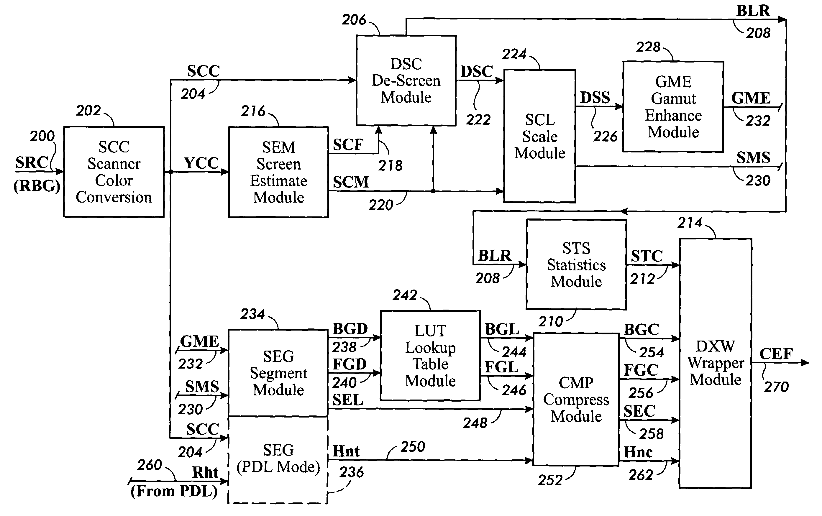
A Gamut Enhance Module (GME) is disclosed for applying 3 independent Tone Reproduction Curves (TRC) to each of the color components of an input image. The implementation is done via three independent and fully programmable 1D lookup tables. The input to the Gamut Enhance Module is the output DSS from a Scaling Module (SCL), representing a scaled and de-screened version of the source image. The output is a gamut-mapped signal GME. The GME unit includes special logic to neutralize (set to gray) or preserve input colors.

Description

CROSS-REFERENCE TO RELATED APPLICATIONS[0001]This application is based on a Provisional Patent Application No. 60 / 393,244 filed Jul. 1, 2002.[0002]The present application is related to the following co-pending applications: Ser. No. 10 / 187,499 entitled “Digital De-Screening of Documents”, Ser. No. 10 / 188,026 entitled “Control System for Digital De-Screening of Documents”, Ser. No. 10 / 188,277 entitled “Dynamic Threshold System for Multiple Raster Content (MRC) Representation of Documents”, Ser. No. 10 / 188,157 entitled “Separation System for Multiple Raster Content (MRC) Representation of Documents”, and Ser. No. 60 / 393,244 entitled “Segmentation Technique for Multiple Raster Content (MRC) TIFF and PDF all filed on Jul. 01, 2002 and all commonly assigned to the present assignee, the contents of which are herein incorporated by reference.BACKGROUND[0003]Documents scanned at high resolutions require very large amounts of storage space. Furthermore, large volume of image data requires su...

Claims


Application Information

Patent Timeline
Patent Type & Authority Patents(United States)
IPC IPC(8): G06K9/00G06K9/40G06K9/54G06T5/40H04N1/407
CPCG06T5/007G06T5/40H04N1/407H04N1/4074G06T5/90
Inventor CURRY, DONALD J.KLETTER, DORONNAFARIEH, ASGHAR
Owner XEROX CORP
Learn More