Method and apparatus for laser line-width compensation

a laser line width and compensation technology, applied in the field of optical communication systems, can solve the problems of significant net optical chromatic dispersion, significant deformation of tuning response, and significant deformation of performance in the region of 1 mhz

Inactive Publication Date: 2007-04-03
RPX CLEARINGHOUSE
View PDF21 Cites 18 Cited by
  • Summary
  • Abstract
  • Description
  • Claims
  • Application Information

AI Technical Summary

Benefits of technology

[0034]The apparatus may also further comprise means for delaying the output signal between the optical emitter and the complex modulator for a period of time adequate to permit the power level detectors to detect the power levels of the output si...

Problems solved by technology

This narrowband noise is often predominantly phase noise.
The performance of optical transmission systems with long-haul optical spans is impacted by significant amounts of net optical chromatic dispersion.
On such systems, the phase noise of the laser source is substantially converted to amplitude noise by the action of the dispersion, at a level that can significantly degrade performance.
However, these effects have different phase responses, so the complex sum of the two effects creates an amalgamated tuning response that severely degrades in the region of 1 MHz.
Frequency tuning does not help amplitude noise, and often creates more amplitude variations, r...

Method used


Image

  • Method and apparatus for laser line-width compensation
  • Method and apparatus for laser line-width compensation
  • Method and apparatus for laser line-width compensation

Examples


Embodiment Construction

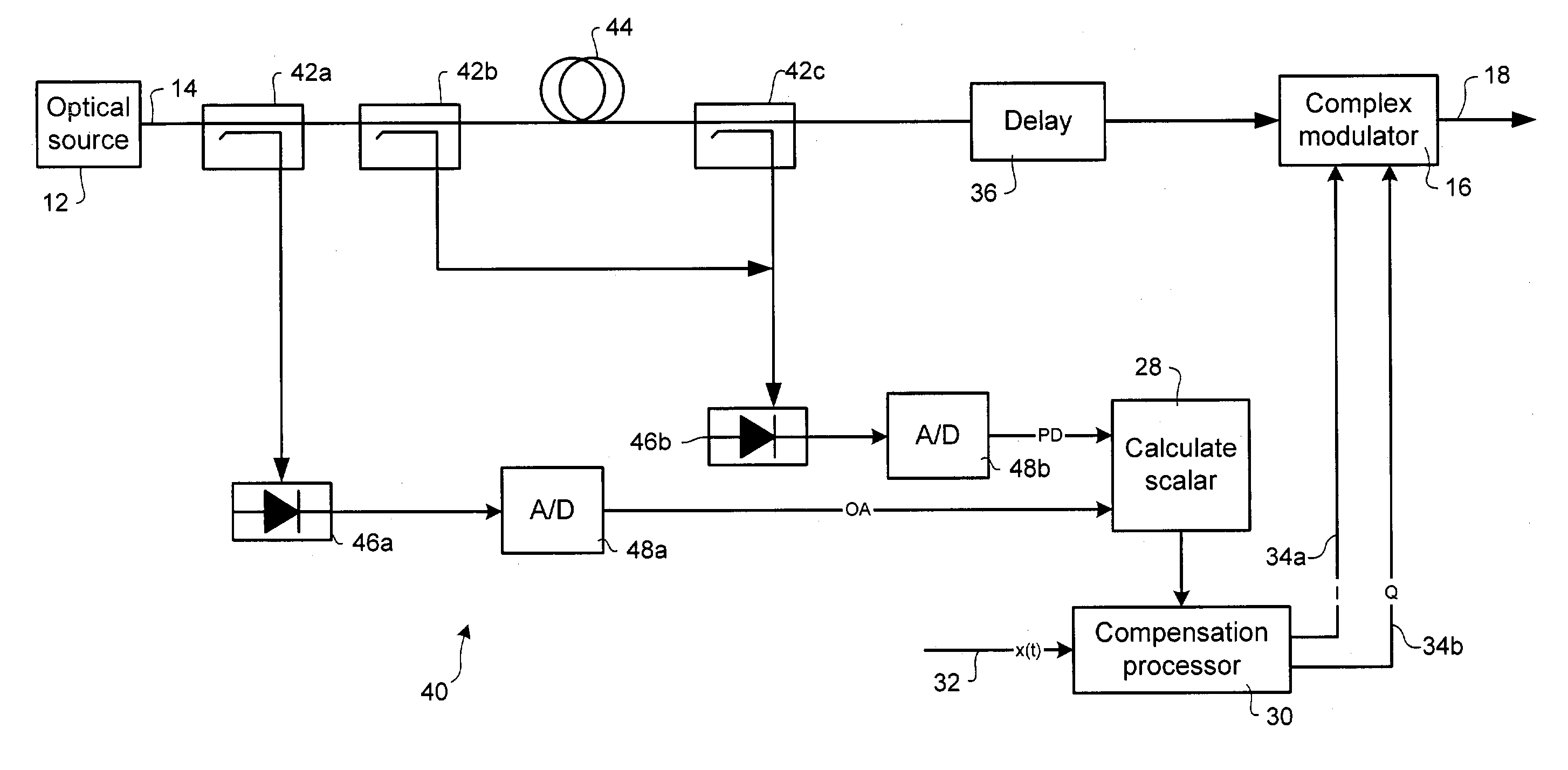
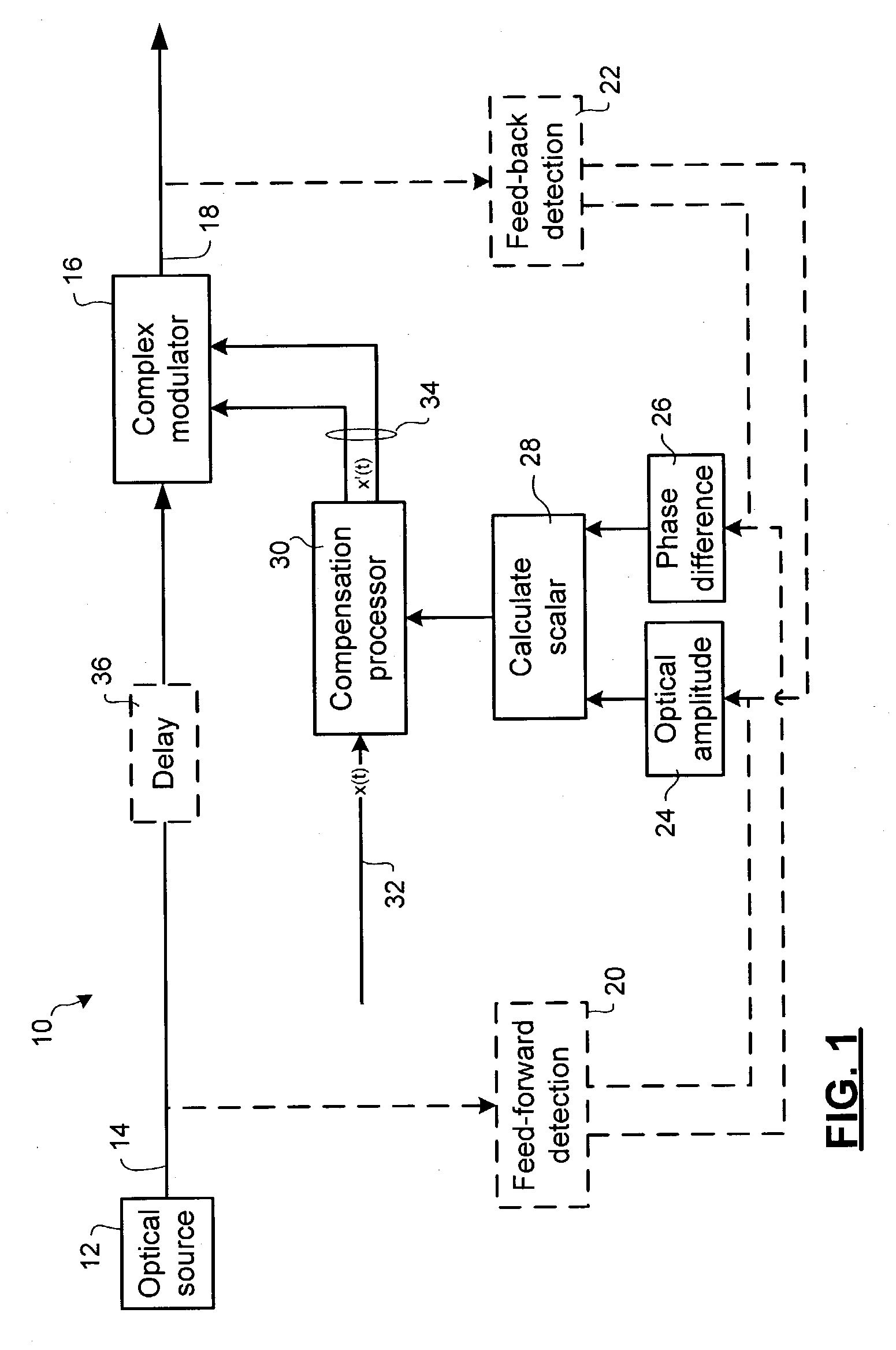
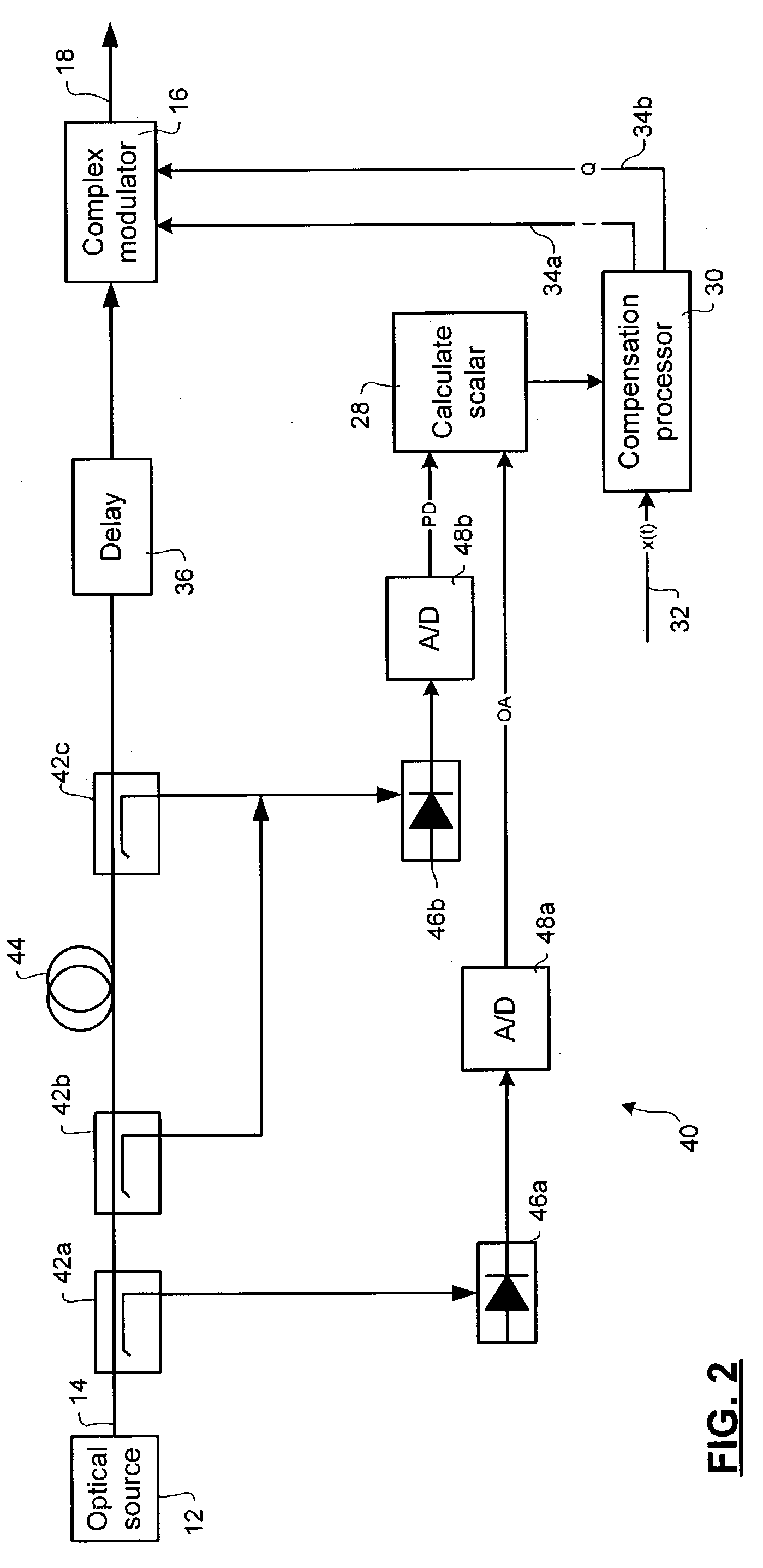
[0042]The invention provides a means for laser line width compensation, to provide a more stable optical signal to serve as a carrier for data in an optical communications system. Noise is detected in an optical output signal emitted by a laser of the optical communications system. The detected noise may be amplitude noise and / or phase noise. The detected noise is used to calculate a compensation scalar. The compensation scalar is used by a compensation processor to modify an input signal containing data to be transmitted by the optical communications system. The optical output signal is delayed in the optical domain while the compensation scalar is calculated and the input signal is modified in the electrical domain. The modified input signal is used to control a complex modulator that modulates the delayed optical output signal to cancel the detected noise while applying the data to be transmitted by the optical communications system.

[0043]FIG. 1 schematically illustrates principa...


PUM


Abstract

Laser line-width compensation is performed by detecting noise in an optical signal output by a laser of an optical communications system and controlling a complex modulator to cancel the detected noise. Line-width compensation can be performed for both amplitude and phase noise in the optical signal. Noise measurements are used to compute a complex scalar. The complex scalar is used by a compensation processor to modify an input signal that is to be transmitted by the optical communications system. The modified input signal controls the complex modulator, which modulates the output signal to cancel the noise.

Description

CROSS-REFERENCE TO RELATED APPLICATIONS[0001]This is the first application filed for the present invention.MICROFICHE APPENDIX[0002]Not Applicable.TECHNICAL FIELD[0003]This invention relates to optical communications systems and, in particular, to a method and apparatus for compensating a line-width of an optical signal output by a laser of an optical transmitter in an optical communications system.BACKGROUND OF THE INVENTION[0004]Optical communications systems are used for economically transferring large volumes of data over long distances. Economies are improved if fiber link length is extended without repeaters. Single-mode lasers are commonly used in long-haul networks. As is well understood in the art, the output of a single-mode laser is composed of phase and amplitude noise that is present in the output optical spectrum, along with desired single spectral tone. The broadband amplitude noise is called Relative Intensity Noise (RIN) measured in dBc. The narrowband noise is usua...

Claims


Application Information

Patent Timeline
IPC IPC(8): H04B10/00H04B10/04
CPCH04B10/505H04B10/50572H04B10/50577H04B10/50593H04B10/50597H04B10/58
Inventor ROBERTS, KIMO'SULLIVAN, MAURICE
Owner RPX CLEARINGHOUSE
Why Eureka
Try Eureka