Article of thermal clothing for covering the underlying area at the gap between a coat sleeve and a glove

a technology of thermal clothing and underlying skin, which is applied in the field of thermal clothing articles, can solve the problems of severe injury, significant discomfort of the person, and exaggerated arm movements, and achieve the effect of preventing the exposure of the underlying skin

Inactive Publication Date: 2007-04-10
GREGORY KATHRYN
View PDF43 Cites 32 Cited by
  • Summary
  • Abstract
  • Description
  • Claims
  • Application Information

AI Technical Summary

Benefits of technology

[0011]Still another object of the present invention is to provide a novel article of thermal clothing which, when worn, does not cover the fingers so as to prevent their reception within the corresponding digits of a fingered glove.
[0012]Yet another object of the present invention is to provide a novel article of thermal clothing which, when worn, does not cover the fingers so as to diminish the wearer's ability to grasp and manipulate objects.
[0013]And another object of the present invention is to provide a novel article of thermal clothing which can be comfortably and conveniently worn under a coat sleeve and a glove so as to protect the area therebetween.
[0016]These and other objects of the present invention are achieved by providing a novel article of thermal clothing which generally comprises a tube having a distal portion terminating in a distal end, a proximal portion terminating in a proximal end, and a side opening formed in the distal portion adjacent to but spaced from the distal end. The tube is formed out of a flexible, somewhat stretchable material capable of providing good thermal insulation. Preferably this material is also water resistant.
[0018]The tube is sized so that it can be snugly fit over the wearer's hand and forearm, with the distal end of the tube being positioned near the midpalm area and the proximal end of the tube being positioned at the forearm area, and with the wearer's thumb extending out through the tube's side opening. When the tube is in this position, the wearer's thumb and fingers will remain completely free and unrestrained. The article of clothing is worn under a glove and the sleeve of a coat so as to bridge the gap therebetween and thereby prevent exposure of the underlying skin to snow and cold air. The article is provided with a pocket for receiving and retaining a warming device. This article of clothing could also be worn alone.

Problems solved by technology

The presence of this cold snow against the underlying skin can cause a person substantial discomfort and, in some cases, may actually lead to serious injury, e.g. frostbite.
Moreover, during some winter activities, exaggerated arm movements may sometimes occur.
Again, this can cause a person significant discomfort, and may possibly even lead to serious injury.
Unfortunately, these elongated mittens tend to be relatively large and cumbersome and may catch against nearby objects, e.g. a piece of machinery.
Unfortunately, since this mitten liner restricts four of the fingers to a single pocket, it cannot be used with a fingered glove.
Furthermore, even when the mitten liner is used with a mitten, the presence of an additional layer of material between four of the fingers and the mitten tends to seriously diminish the wearer's ability to grasp and manipulate objects.
Unfortunately, these known devices provide significant therapeutic compression and support to the wearer's injured wrist area and, in the case of the McLaurin-Smith device, also provide significant skin surface stimulation to the wearer.
Thus, such physical therapy garments are generally unsuitable for winter activities that are undertaken by uninjured persons.

Method used


Image

  • Article of thermal clothing for covering the underlying area at the gap between a coat sleeve and a glove
  • Article of thermal clothing for covering the underlying area at the gap between a coat sleeve and a glove
  • Article of thermal clothing for covering the underlying area at the gap between a coat sleeve and a glove

Examples


Embodiment Construction

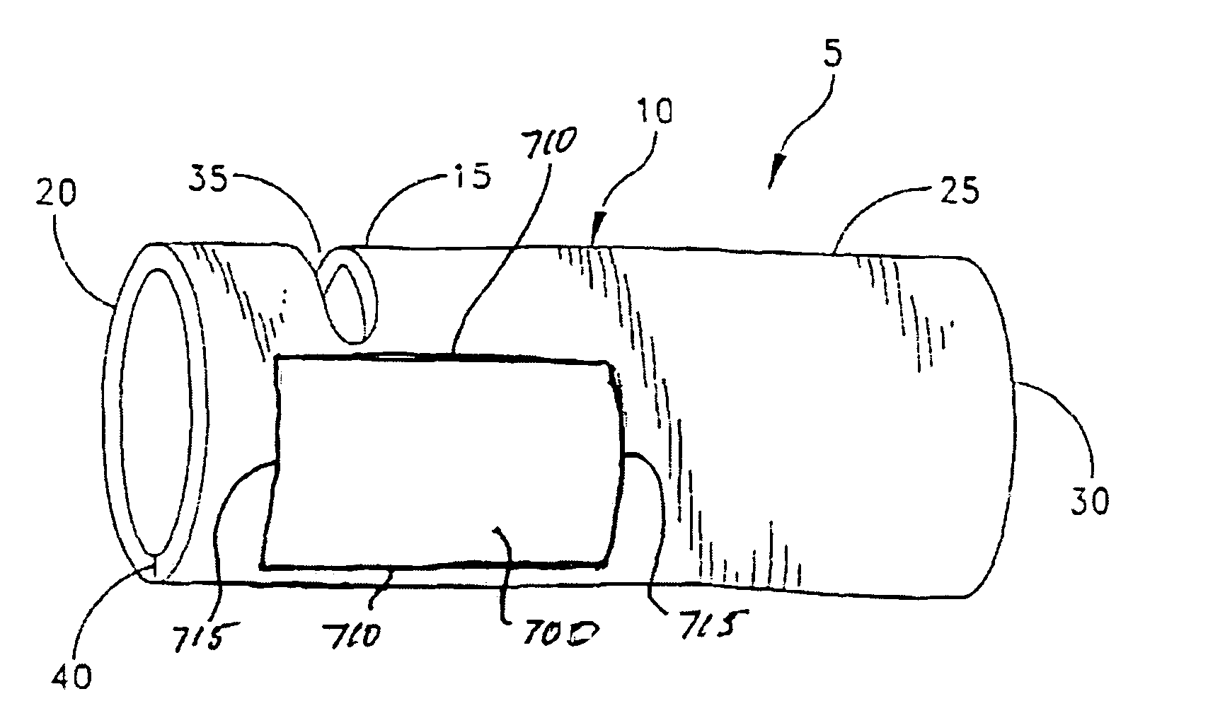
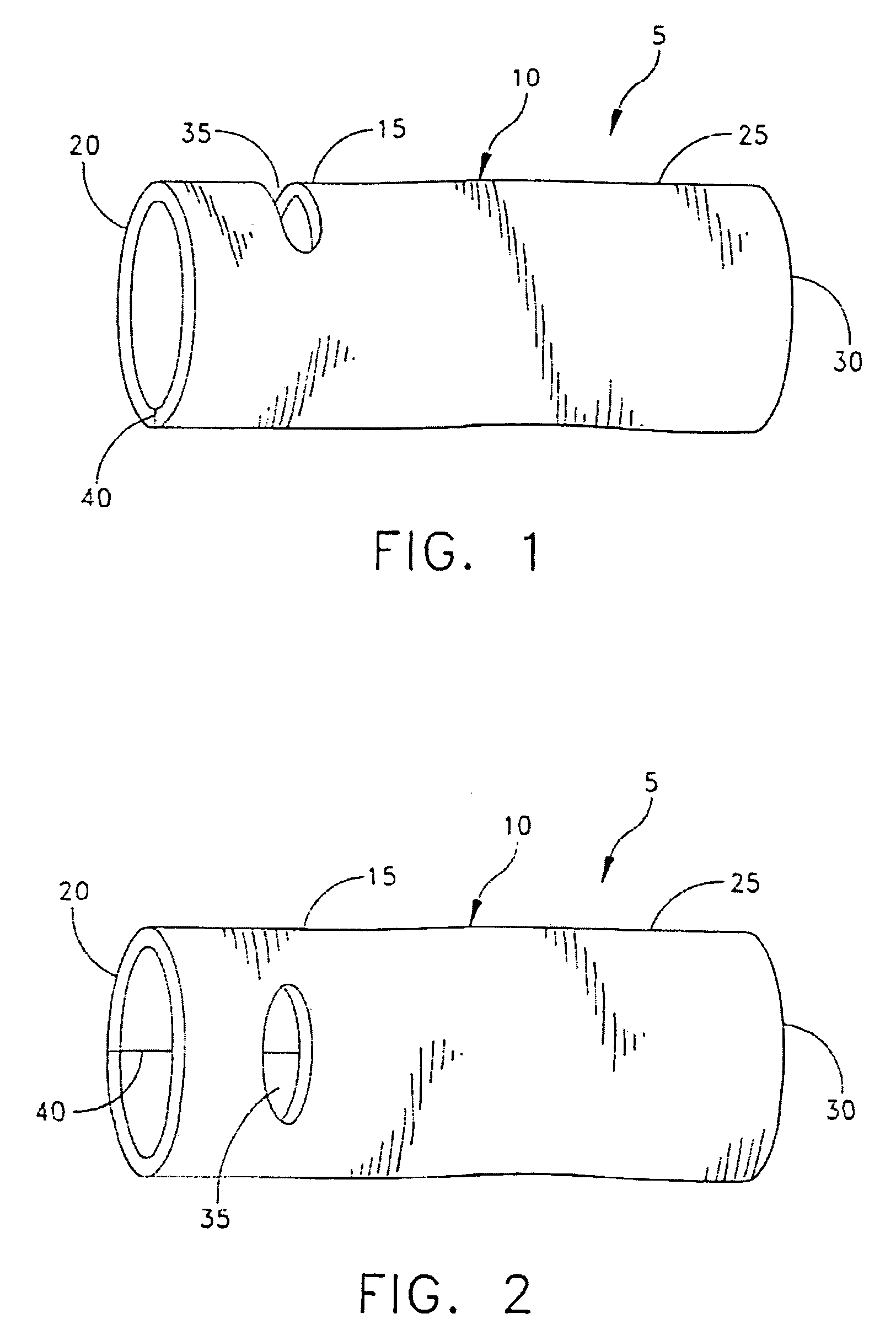
[0033]Looking first at FIGS. 1 and 2, there is shown an article of thermal clothing 5 which generally comprises a tube 10.

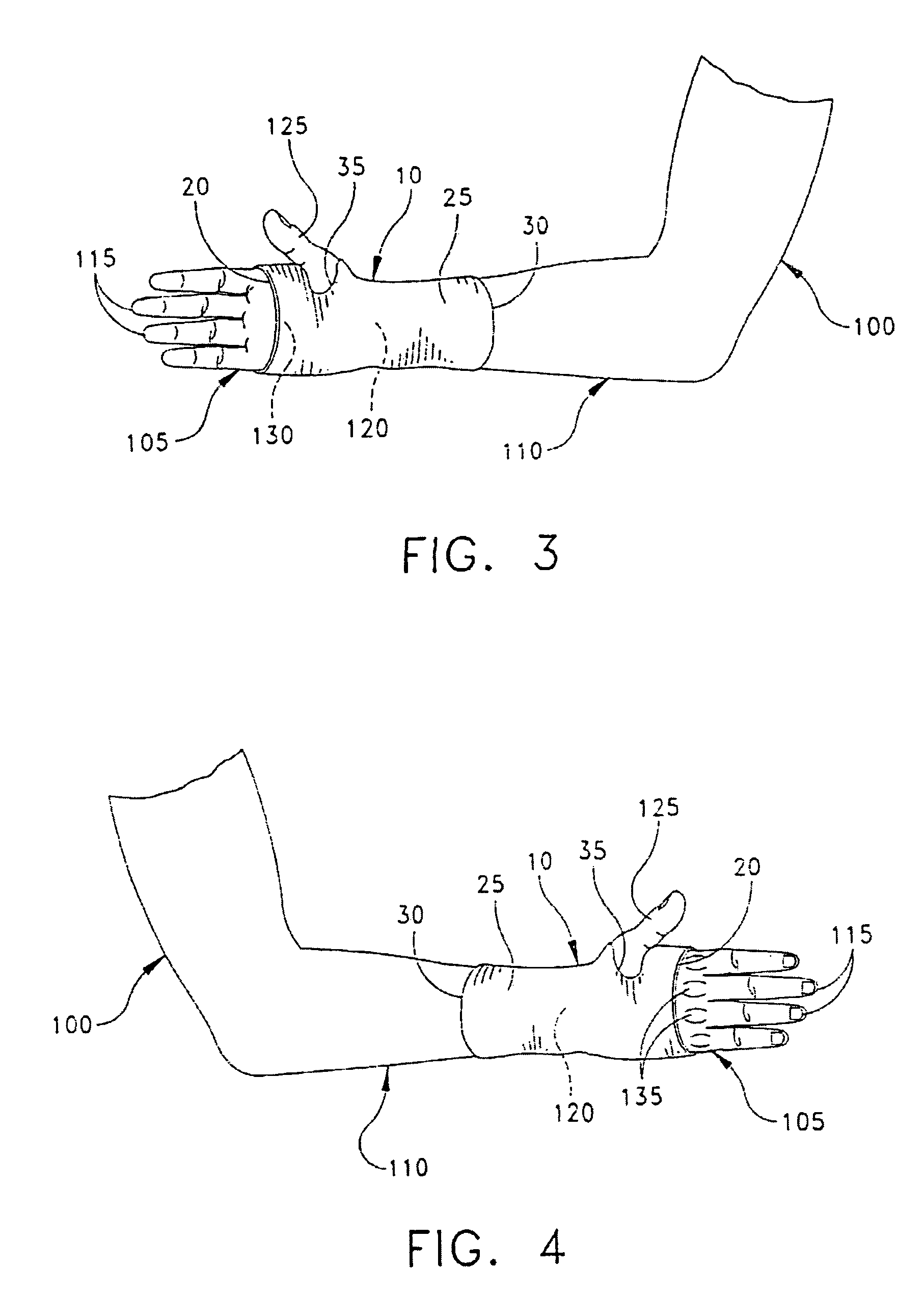
[0034]Tube 10 comprises a distal portion 15 terminating in a distal end 20 and a proximal portion 25 terminating in a proximal end 30. A side opening 35 is formed in distal portion 15 adjacent to but spaced from distal end 20. Side opening 35 is oriented in a substantially transverse direction relative to the tube's longitudinal axis (see, e.g. FIGS. 1–4). Side opening 35 communicates with the interior of tube 10.

[0035]Tube 10 is formed out of a material which is flexible, somewhat stretchable, and which is capable of providing good thermal insulation. Preferably, tube 10 is also made out of a material which is water resistant. In practice, it has been found that tube 10 may be easily fabricated out of a woven, relatively resilient fabric sheet which is sewn together at a seam 40 so as to form the tube. It has also been found that, if desired, stitching 42 (FIG. ...


PUM


Abstract

An article of thermal clothing for covering an underlying area at a gap between a coat sleeve and a glove. The article of clothing includes a tube having a distal portion terminating in a distal end, a proximal portion terminating in a proximal end, and a side opening formed in the distal portion adjacent to but spaced from the distal end. The tube is sized to snugly fit over a wearer's hand and forearm so that the distal end of the tube is positioned near a midpalm area of the hand. The proximal end of the tube is positioned at the forearm area, and the wearer's thumb extends out through the tube's side opening. The tube is formed out of a flexible, stretchable material providing good thermal insulation. A pocket is fixed to the tube and is adapted to receive and retain a warming device.

Description

REFERENCE TO COPENDING APPLICATION[0001]This is a continuation-in-part of U.S. patent application Ser. No. 10 / 196,352, filed Jul. 16, 2002 in the name of Kathryn Gregory, by Susan B. Gregory, Legal Representative, (which patent application is hereby incorporated herein by reference), now abandoned, which is, in turn, a continuation of U.S. patent application Ser. No. 09 / 243,274, filed Feb. 2, 1999 in the name of Kathryn Gregory, by Susan B. Gregory, Legal Representative, for ARTICLE OF THERMAL CLOTHING FOR COVERING THE UNDERLYING AREA AT THE GAP BETWEEN A COAT SLEEVE AND A GLOVE, now U.S. Pat. No. 6,418,561, which is in turn a continuation-in-part of prior application Ser. No. 08 / 669,653, filed Jun. 24, 1996 by Kathryn Gregory, by Susan B. Gregory, Legal Representative, for ARTICLE OF THERMAL CLOTHING FOR COVERING THE UNDERLYING AREA AT THE GAP BETWEEN A COAT SLEEVE AND A GLOVE, now U.S. Pat. No. 5,864,886, which is in turn a continuation-in-part of prior application Ser. No. 08 / 318...

Claims


Application Information

Patent Timeline
Patent Type & Authority Patents(United States)
IPC IPC(8): A41D19/00A41D13/08
CPCA41D13/08A41D13/088A41D13/0005A41D2400/10
Inventor GREGORY, KATHRYN
Owner GREGORY KATHRYN
Why Eureka
Try Eureka