Transfer device

a technology of transferring device and patient, which is applied in the field of transferring device, can solve the problems of transferring patient while keeping patient posture, requiring many hands, and difficult work, and achieves the effect of cost reduction and simple structur

Active Publication Date: 2007-04-10
DAIHEN CORP
View PDF12 Cites 47 Cited by
  • Summary
  • Abstract
  • Description
  • Claims
  • Application Information

AI Technical Summary

Benefits of technology

[0012]It is, therefore, an object of the present invention to provide a transfer device which is capable of solving the above problems of the prior art structure, with a simple structure which contributes to cost reduction. The transfer device of the present invention is capable of transferring e.g. a patient to a stretcher regardless of the position and posture of the patient on the bed.

Problems solved by technology

Such work is hard, requiring many hands.
Further, the work for transferring the patient while keeping the posture of the patient so as not to damage the affected part is very difficult and need be performed carefully.
Firstly, a patient lying as inclined relative to an edge of the bed cannot be properly placed on the transfer mechanism. Specifically, a patient on a bed rarely lies in parallel with an edge of the bed and mostly lies as inclined. Further, depending on the medical condition, the posture of the patient may not be changed easily. In such a case, the transfer device disclosed in the above Patent Document lifts and place the patient obliquely, so that the posture of the patient on the transfer mechanism becomes unstable. Moreover, even on the stretcher, manual work for putting the patient within the width of the stretcher need be performed. As noted above, depending on the medical condition, such easy posture change of the patient may worsen the condition of the patient.
Secondly, a patient lying far from the edge of the bed by a distance larger than the width of the stretcher cannot be dealt with. This is because the transfer mechanism advancing from the stretcher set alongside the bed cannot reach the patient. Although a patient whose condition is not severe may be moved manually on the bed, the transfer device cannot deal with a patient who is in critical condition and whose posture cannot be changed easily.
Therefore, the entire apparatus is complicated, and the manufacturing cost is extremely high.

Method used


Image

  • Transfer device
  • Transfer device
  • Transfer device

Examples


first embodiment

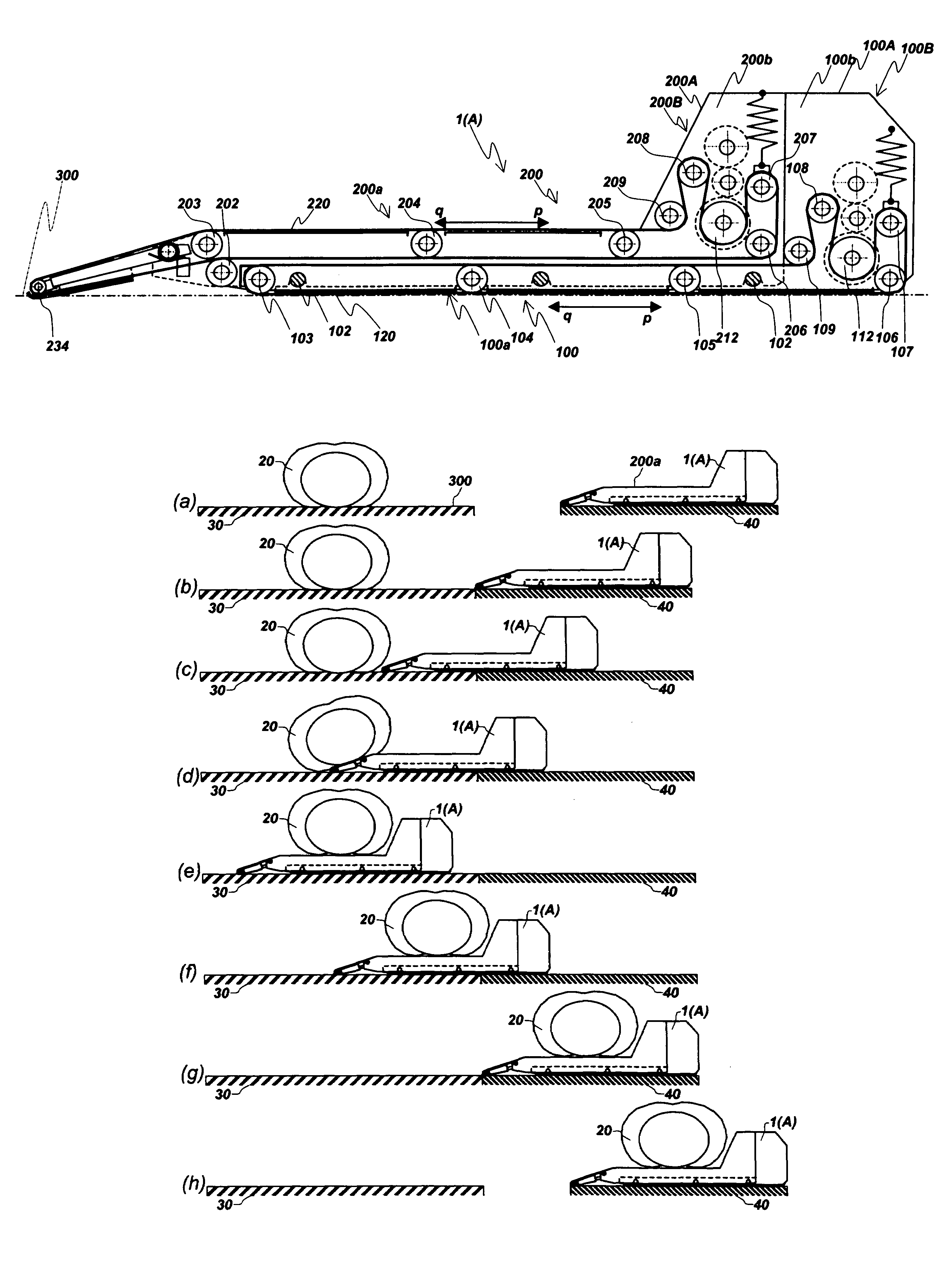
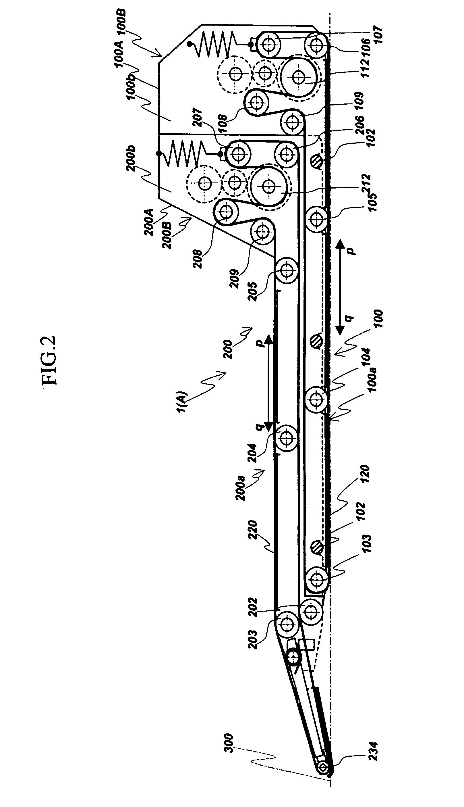
[0058]FIGS. 1–18 show transfer device assembly according to the present invention.

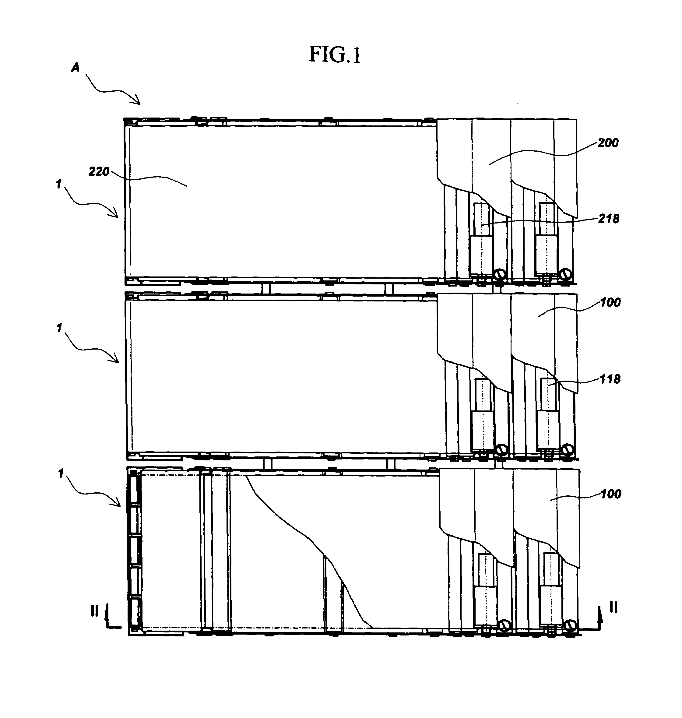
[0059]As shown in FIG. 1, the transfer device assembly A comprises a plurality of transfer devices 1 connected together in the widthwise direction. In the illustrated embodiment, three transfer devices are connected together. The width of the transfer device assembly A is so selected as to be sufficient for carrying a patient on a bed, and hence the width of each transfer device 1 is determined depending on the selected width of the assembly. As shown in FIGS. 2–4, each transfer device 1 includes a lower mechanism 100 and an upper mechanism 200 stacked together in the vertical direction.

[0060]The upper mechanism 100 and the lower mechanism 200 of each transfer device include endless belts 120, 220, respectively, which are rotatable independently of each other and each of which is rotatable selectively in opposite directions. Driving portions 100B, 200B for driving the endless belts 120 and 220, respect...


PUM


Abstract

A transfer device includes a lower mechanism and an upper mechanism stacked on the lower mechanism. The lower mechanism includes a first endless belt, and the upper mechanism includes a second endless belt. The first and the second endless belts are operable independently of each other for forward and backward circulation. The first endless belt is driven by a first driving unit disposed at one end of the lower mechanism as viewed in the traveling direction of the first endless belt. The second endless belt is driven by a second driving unit disposed at one end of the upper mechanism as viewed in the traveling direction of the second endless belt. A plurality of transfer devices connected in their widthwise direction constitute a transfer device assembly.

Description

BACKGROUND OF THE INVENTION[0001]1. Field of the Invention[0002]The present invention relates to a transfer device which is suitable for use in transferring a patient between a bed and a stretcher with wheels (gurney), for example. The transfer device according to the present invention is also suitable for changing the location of e.g. a piece of wooden furniture without damaging it.[0003]2. Description of the Related Art[0004]In a hospital, nursing facility or the like, a stretcher is used for transporting a patient who cannot walk or has difficulty in walking from a hospital room to an examination room, a treatment room or a bath, for example. Such a stretcher comprises a rest base having a width and a length sufficient for carrying a patient and supported by legs with wheels at a height generally equal to a bed surface. To transfer the patient between the bed and the stretcher, the stretcher is set alongside the bed.[0005]The transfer of the patient is generally performed by lift...

Claims


Application Information

Patent Timeline
Patent Type & Authority Patents(United States)
IPC IPC(8): A61G7/14B65G15/22A61G1/00A61G1/02A61G7/10B65G7/02
CPCA61G7/1032A61G7/1036A61G7/1065A61G7/1011A61G2200/32
Inventor KASAGAMI, FUMIOHOJO, FUMIOHYODO, HIDEAKI
Owner DAIHEN CORP
Why Eureka
Try Eureka