Micro-channel tubing evaporator

a micro-channel tubing and evaporator technology, which is applied in the field of ice machines, can solve the problems of large number of parts, easy damage of steel plates, and high cost of spare parts for ice machines, and achieve the effect of facilitating the production of ice pieces

Inactive Publication Date: 2007-04-10
FELDMAN ELAN +1
View PDF19 Cites 45 Cited by
  • Summary
  • Abstract
  • Description
  • Claims
  • Application Information

AI Technical Summary

Problems solved by technology

There are many problems with the commercial ice machines.
The large number of parts contributes to ice machine break downs.
Further, spare parts for ice machines are expensive to obtain or fabricate.
Evaporator plates are also often constructed using thin copper or stainless steel plates that are easily damaged.
This disclosed embodiment is relatively expensive and requires a great deal of labor to form the evaporator plate.
The evaporator plate and plastic grids are expensive to replace if they are damaged.

Method used


Image

  • Micro-channel tubing evaporator
  • Micro-channel tubing evaporator
  • Micro-channel tubing evaporator

Examples


Embodiment Construction

)

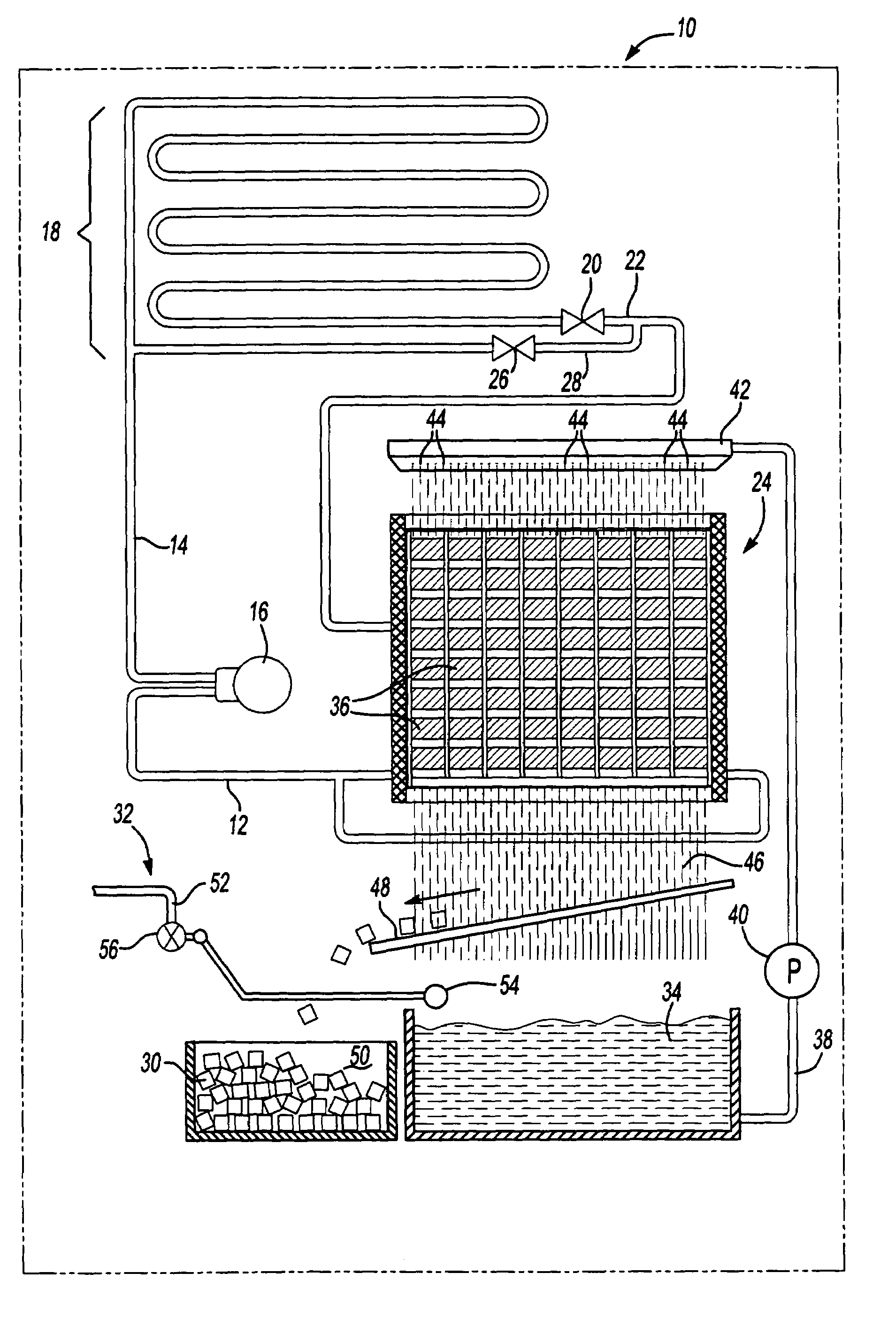
[0025]Referring to FIG. 1, a refrigeration system 10 is illustrated that includes a suction line 12, a discharge line 14, a compressor 16, and condenser coils 18. Refrigerant vapor is circulated through the compressor 16 to the discharge line 14. The refrigerant vapor in the discharge line 14 is then circulated through the condenser coils 18 to condense the refrigerant vapor received from the compressor 16 into a liquid refrigerant. The condenser coils 18 have a refrigerant valve 20 which is opened to circulate the liquid refrigerant through a refrigerant line 22 to an evaporator assembly 24.

[0026]A hot gas valve 26 in a hot gas line 28 are provided to control circulation of refrigerant vapor in the refrigerant line 22. Refrigerant vapor in the refrigerant line 22 may then be circulated to the evaporator assembly 24 to release ice pieces 30 from the evaporator assembly 24 once the ice pieces 30 reach a desired size.

[0027]FIG. 1 also shows the distribution of water through the refri...


PUM


Abstract

An ice cube making machine having an evaporator assembly on which ice is formed. The evaporator assembly is constructed using micro-channel tubing that provides several channels for the flow of refrigerant within the channels. Liquid refrigerant flowing through the channels causes ice to form on the outer surfaces of the micro-channel tubing over which water flows. Refrigerant vapor is circulated through the channels to release the ice cubes from the micro-channel tubing of the evaporator assembly.

Description

BACKGROUND OF THE INVENTION[0001]1. Field of the Invention[0002]This invention relates to ice machines and more particularly to making ice on an evaporator assembly.[0003]2. Background Art[0004]Commercial ice machines are used in hotels, restaurants, and other public establishments.[0005]Refrigerant passes through copper tubing in a commercial ice machine. The copper tubing is generally adjacent to an evaporator plate that comprises a flat metal plate. The evaporator plate is cooled by refrigerant flowing through the copper tubing. Ice is formed on a surface of the evaporator plate as water flows over the surface and is cooled. When the ice reaches its desired size, a hot gas defrost is run through the copper tubing and releases the ice cubes from the evaporator plate. The ice cubes fall into an ice bin after they are released and are stored for later use.[0006]There are many problems with the commercial ice machines. There are often many parts associated with the evaporator assembl...

Claims


Application Information

Patent Timeline
Patent Type & Authority Patents(United States)
IPC IPC(8): F25C1/12
CPCF25B39/02F25C1/12F28F1/022F25C2400/02F28F2275/02
Inventor FELDMAN, ELANSHIMONI, DORON
Owner FELDMAN ELAN
Why Eureka
Try Eureka