Target system

a target system and target technology, applied in the field of target systems, can solve the problems of difficult use, relatively complicated system disclosed in the above us patent specification, and inability to move, and achieve the effect of durable design

Inactive Publication Date: 2007-04-10
HONESTAS
View PDF7 Cites 46 Cited by
  • Summary
  • Abstract
  • Description
  • Claims
  • Application Information

AI Technical Summary

Benefits of technology

[0010]The object of the present invention is to overcome the drawbacks of prior art and to achieve a new type of target system provided with a pop-up target and actuated by an electric motor, which system is of very durable design and is additionally of modular construction.
[0012]The target system of the invention is very simple and durable, especially because welded joints have been eliminated from the parts subject to stress, thus achieving a durable construction. In addition, the target system of the invention is of light weight, so it can be portable, and no special transport equipment is needed for relocation of the target system. Thanks to the modular construction, individual parts are of light weight, typically below 20 kg, and e.g. broken or worn parts can be replaced in a rapid and simple manner. Thus, if necessary, a single person can move, assemble and disassemble the target system.
[0013]Moreover, the target system of the invention makes it possible to implement a reactive and relocatable target system that can be used e.g. with a large variety of portable-firearm calibers.

Problems solved by technology

A drawback with pneumatic target systems is their large size, which means that moving them e.g. for transportation requires transport equipment, and in addition, they often have to be immovably installed.
The system disclosed in the above US patent specification is relatively complicated.
Moreover, it is relatively weak in construction e.g. because of the welded joints used in the target, so it will easily break and therefore does not tolerate hard use.
The problem of the prior art as shown in U.S. Pat. No. 4,979,752 is the heavy and bulky construction of the apparatus, especially as the actuating means include an air

Method used


Image

  • Target system
  • Target system
  • Target system

Examples


Embodiment Construction

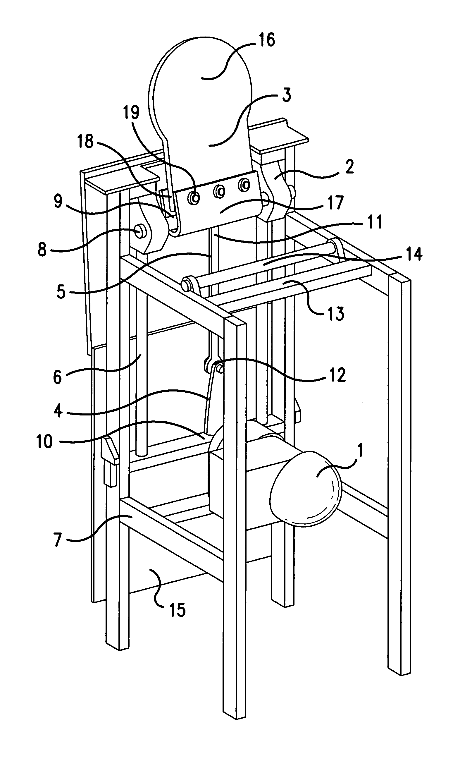
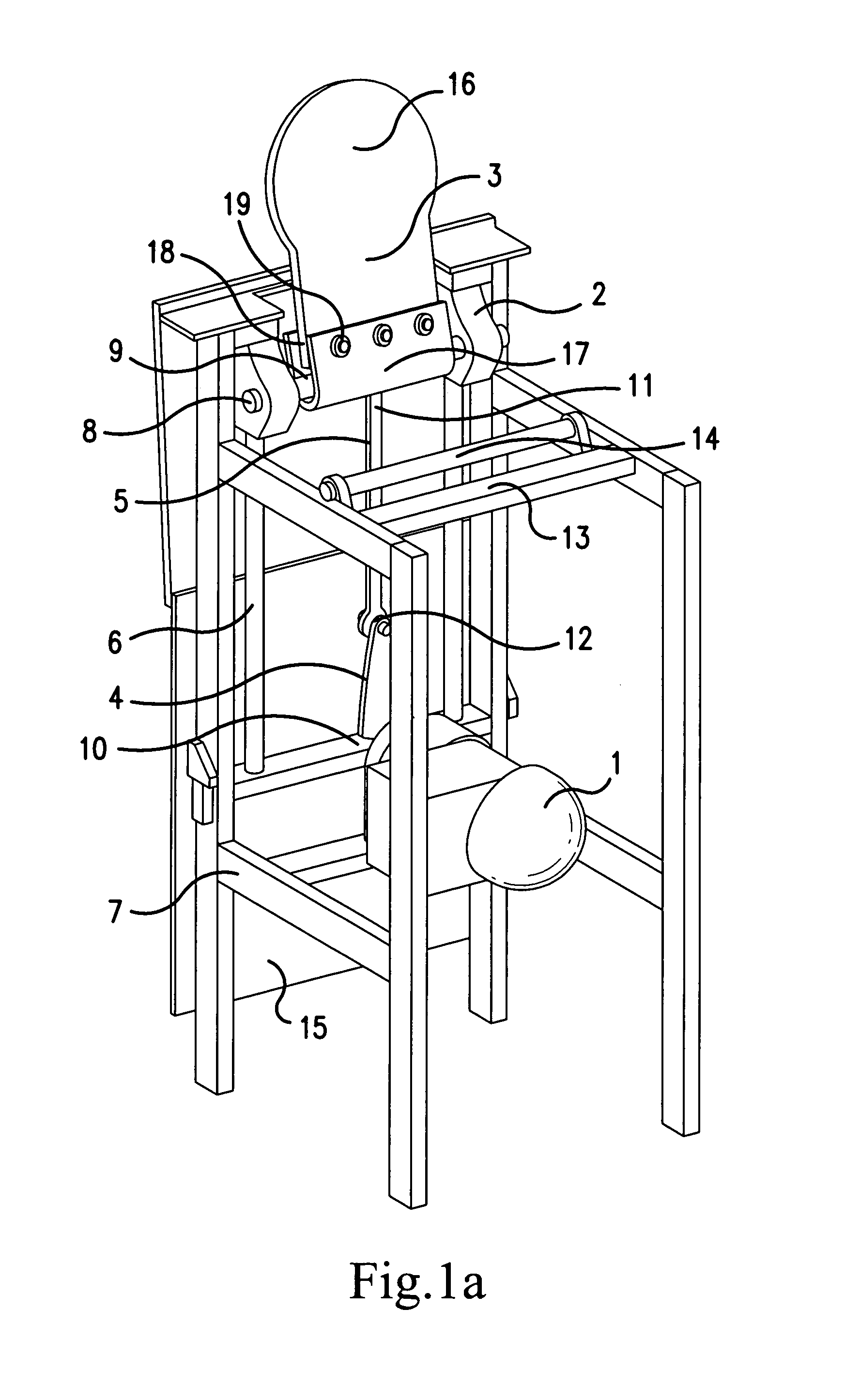
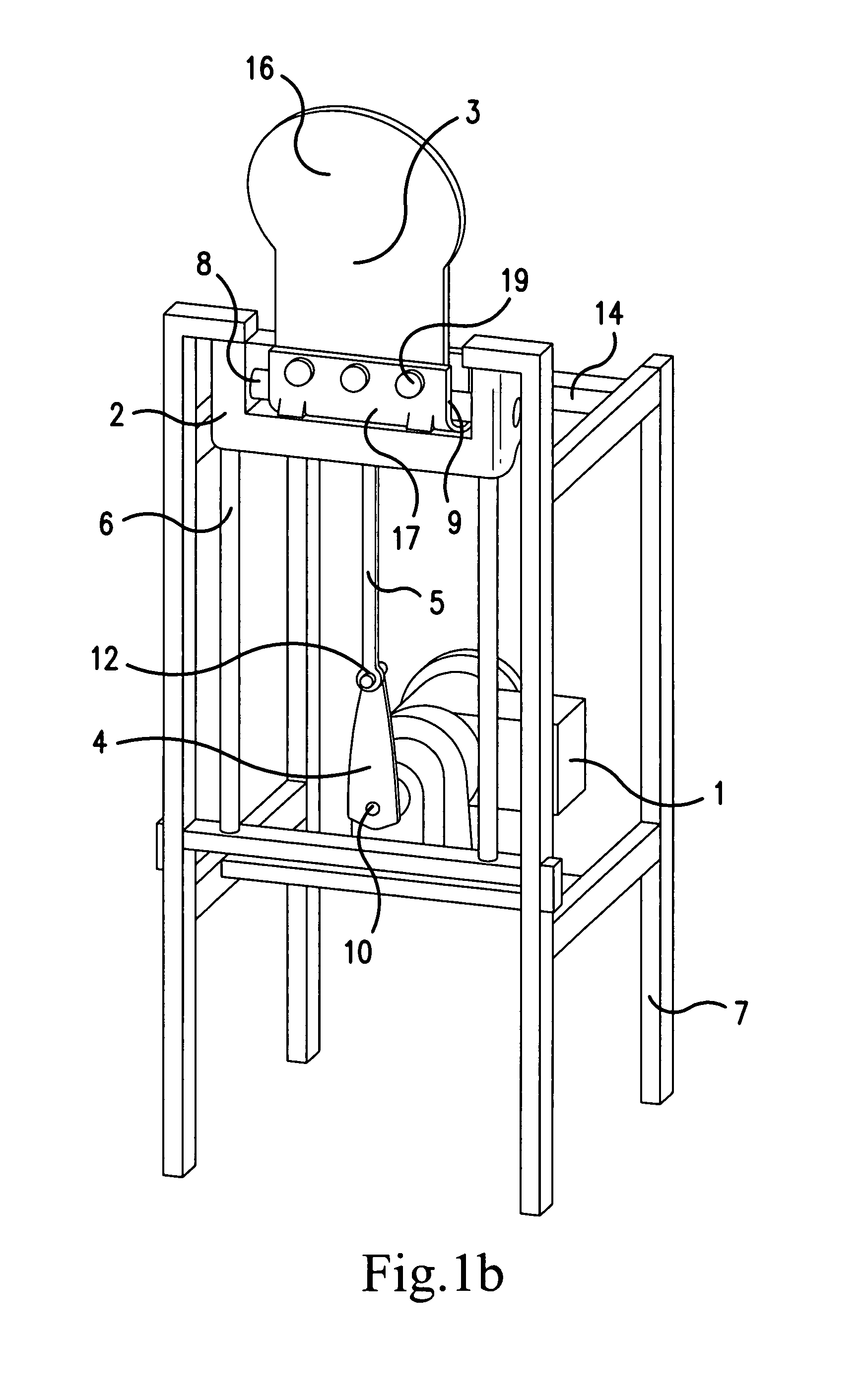
[0018]The target system presented in FIGS. 1a and 1b consists of five main components: a target 3, a carriage 2, guide rails 6, an electric motor 1 with levers 4, 5 and a frame 7. The operation of the system is controlled by a control unit (not shown) provided with a computer. The target 3 is a steel plate impenetrable to a bullet.

[0019]The motor 1 located in the lower part of the apparatus moves the carriage 2 along a pair of vertical guide rails 6 by means of levers 4, 5 connected to it. The target 3 is hinged at its lower end on the carriage by horizontal shaft 8 provided in the carriage and a transverse horizontal hole in the lower edge of the target. The levers 4, 5 are connected to the rotating axle 10 of the motor 1 and to a pivot pin 11 at the lower edge of the carriage. In addition, the levers are connected to each other by a pivot pin 12. The motor 1 and the guide rails guiding the carriage may be fixedly mounted on the frame 7.

[0020]In position A (FIG. 2a), the carriage 2...


PUM


Abstract

A target system for light infantry weapons including a target overturnable by an impact and an actuating mechanism configured to move the target. The target is connected to the actuating mechanism via a pivot structure. Further, the actuating mechanism includes a lifter configured to lift the target to a substantially upright position, a vertical rail system and a carriage vertically moveable along the vertical rail system, and an electric motor configured to move the carriage along the vertical rail system. Also, the pivot structure is arranged on the carriage, and the lifter includes a supporting lifter device, against which the target falls when hit and which, when the carriage is lowered, lifts the target to the substantially upright position utilizing the movement of the carriage and an inertia of the target. In addition, the target system is portable and of modular construction.

Description

BACKGROUND OF THE INVENTION[0001]1. Field of the Invention.[0002]The present invention relates to a target system provided with a pop-up target.[0003]2. Discussion of the Background[0004]Target systems with pop-up targets designed for light infantry weapons comprise a metallic target, which falls down when hit by a bullet, and an actuating mechanism for actuating the target, i.e. for lifting it up again and moving it. The actuating mechanism may be protected by a shield plate placed in front of it. To control the actuating mechanism, a control apparatus provided with a computer may be connected to the actuating mechanism. Hits can be detected e.g. by using a hit detector arranged in conjunction with the target.[0005]The actuating mechanism may be electrically operated, but it may also be operated pneumatically. A drawback with pneumatic target systems is their large size, which means that moving them e.g. for transportation requires transport equipment, and in addition, they often h...

Claims


Application Information

Patent Timeline
Patent Type & Authority Patents(United States)
IPC IPC(8): F41J7/04
CPCF41J7/04
Inventor KUOSA, RISTO
Owner HONESTAS
Why Eureka
Try Eureka