

Offset joint between structural members in a vehicle frame assembly to facilitate a coating process
- Summary
- Abstract
- Description
- Claims
- Application Information
AI Technical Summary
Benefits of technology
Problems solved by technology
Method used
Image

Examples
first embodiment
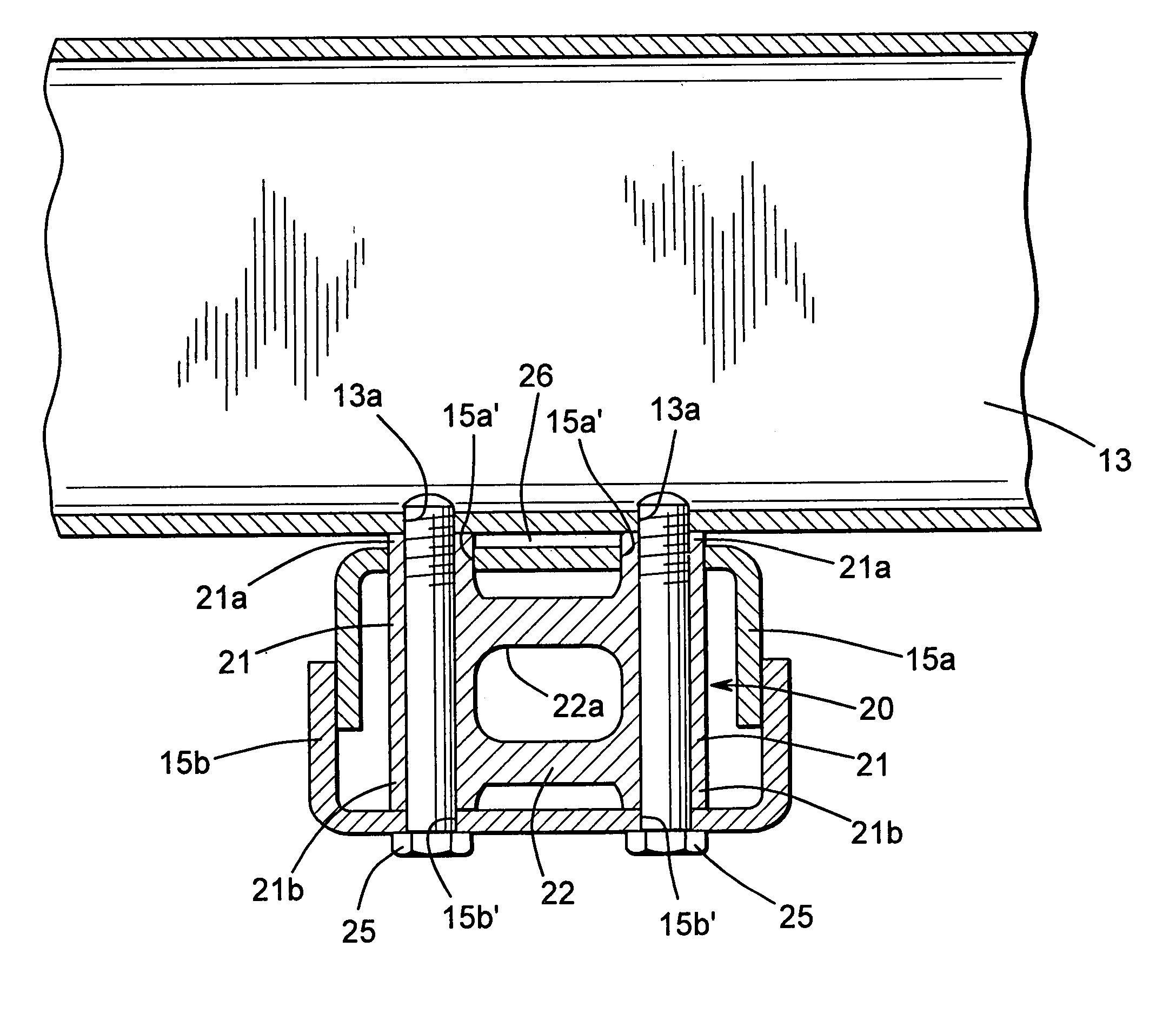
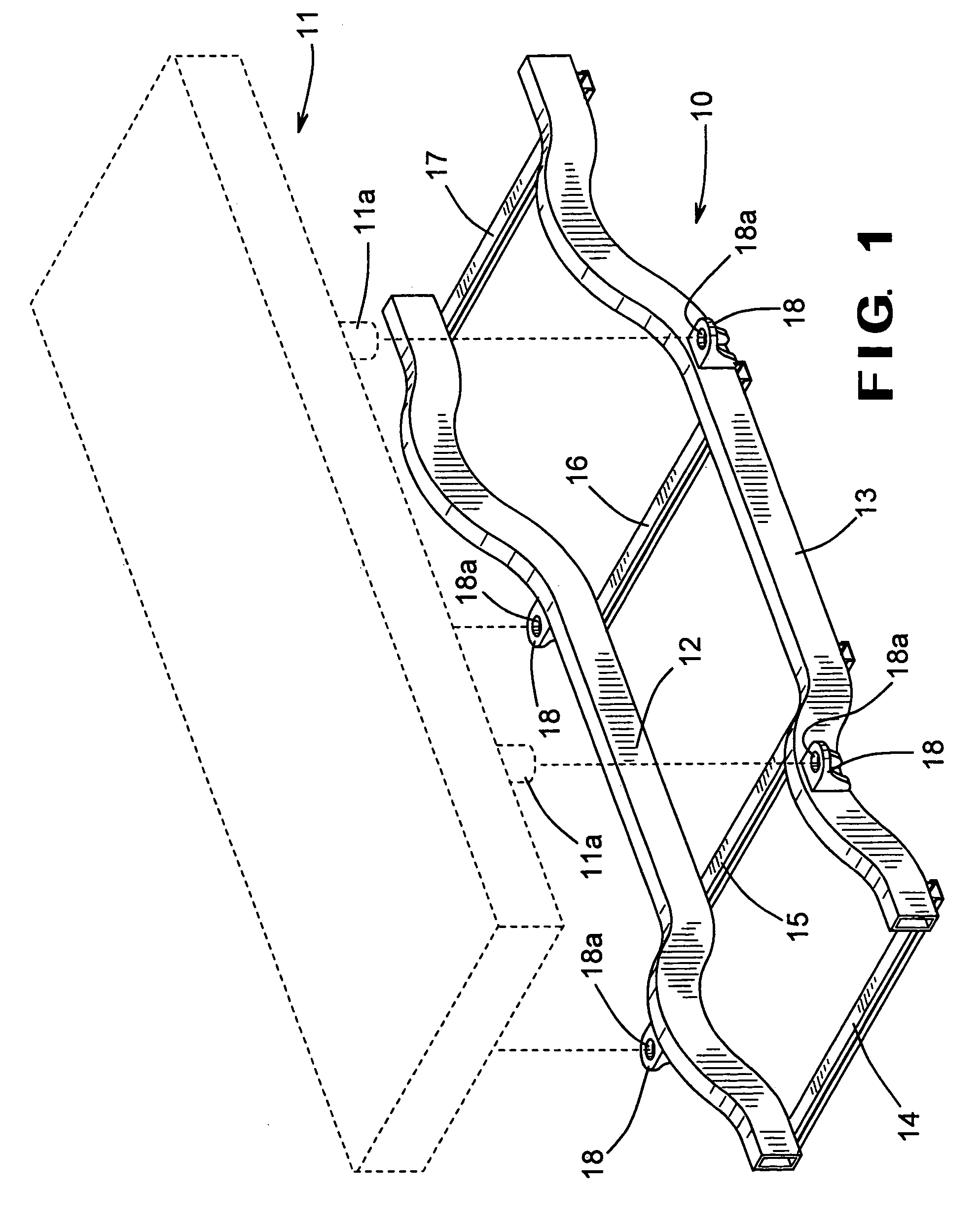
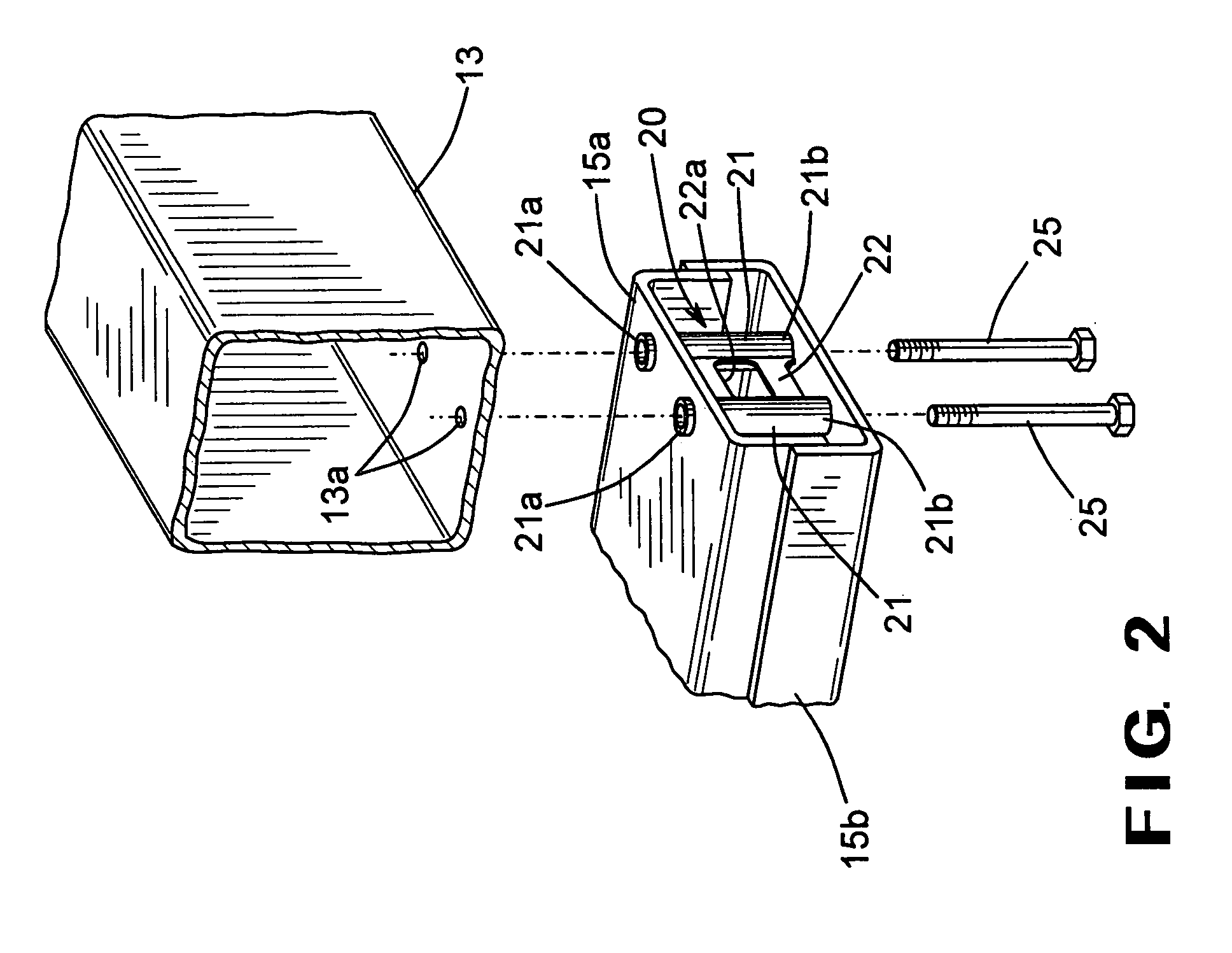
[0017]At each location where two or more of the structural members 12 through 17 are connected together to form the vehicular body and frame assembly, a joint is defined. The structure of one of such joints between the side rail 13 and the cross member 15 is illustrated in detail in FIGS. 2, 3, and 4. As shown therein, the cross member 15 is formed from first and second C-shaped structural members 15a and 15b that are oriented to face inwardly toward one another and are secured together to form the closed channel structural member. The first C-shaped structural member 15a has a pair of apertures 15a′ (see FIG. 4) formed through the web portion thereof. Similarly, the second C-shaped structural member 15b has a pair of apertures 15b′ (see FIG. 4) formed through the web portion thereof. Preferably, the apertures 15a′ formed through the first C-shaped structural member 15a are respectively aligned with the apertures 15b′ formed through the second C-shaped structural member 15b. The pur...
second embodiment
[0022]FIG. 5 is an enlarged perspective view of a cross member, indicated generally at 30, that is adapted for use in a joint with the side rail 13 illustrated in FIGS. 1, 2, and 4 in accordance with this invention. As above, the cross member 30 is formed from first and second C-shaped structural members 30a and 30b that are oriented to face inwardly toward one another and are secured together to form the closed channel structural member. The first C-shaped structural member 30a has a pair of apertures 30a′ formed through the web thereof. Similarly, the second C-shaped structural member 30b has a pair of apertures (not shown) formed through the web thereof. Preferably, the apertures 30a′ formed through the first C-shaped structural member 30a are respectively aligned with the apertures formed through the second C-shaped structural member 30b. The upper surface of the first C-shaped structural member 30a has one or more raised darts 31 or similar embossments formed thereon. Each of t...
third embodiment
[0023]FIG. 6 is an enlarged perspective view of a cross member, indicated generally at 40, that is adapted for use in a joint with the side rail 13 illustrated in FIGS. 1, 2, and 4 in accordance with this invention. As above, the cross member 40 is formed from first and second C-shaped structural members 40a and 40b that are oriented to face inwardly toward one another and are secured together to form the closed channel structural member. The first C-shaped structural member 40a has a pair of apertures 40a′ formed through the web thereof. Similarly, the second C-shaped structural member 40b has a pair of apertures (not shown) formed through the web thereof. Preferably, the apertures 40a′ formed through the first C-shaped structural member 40a are respectively aligned with the apertures formed through the second C-shaped structural member 40b. The upper surface of the first C-shaped structural member 40a has one or more raised dimples 41 or similar embossments formed thereon. Each of...
PUM
 Abstract
Description
Claims
Application Information