Electrical connector for a chip module

a chip module and electrical connector technology, applied in the direction of fixed connections, coupling device connections, electrical apparatus construction details, etc., can solve the problems of large space occupation, inability to tightly arrange, and large distance between two conductive terminals, so as to achieve fast transmission between electronic components and pcb, and reduce the effect of inductor

Inactive Publication Date: 2007-04-10
LOTES
View PDF5 Cites 17 Cited by
  • Summary
  • Abstract
  • Description
  • Claims
  • Application Information

AI Technical Summary

Benefits of technology

[0006]The objective of this invention is to provide an innovative design of a kind of electrical connector that can be tightly arranged and at the same time realize the fast communication between electronic component and PCB.
[0008]Comparing to the present art, the electrical connector of this invention can be tightly arranged, and can effectively reduce inductor effect, and better meets the need of high frequency circuits, thus realizing the fast transmission between electronic component and PCB.

Problems solved by technology

This results in the distance between two conductive terminals becoming too large and cannot be tightly arranged.
The shape of the terminal is also quite complicated and takes up a larger space.
It is also prone to generate higher inductor effect with the neighboring terminal, which is not in favor of high frequency transmission.

Method used


Image

  • Electrical connector for a chip module
  • Electrical connector for a chip module
  • Electrical connector for a chip module

Examples


Embodiment Construction

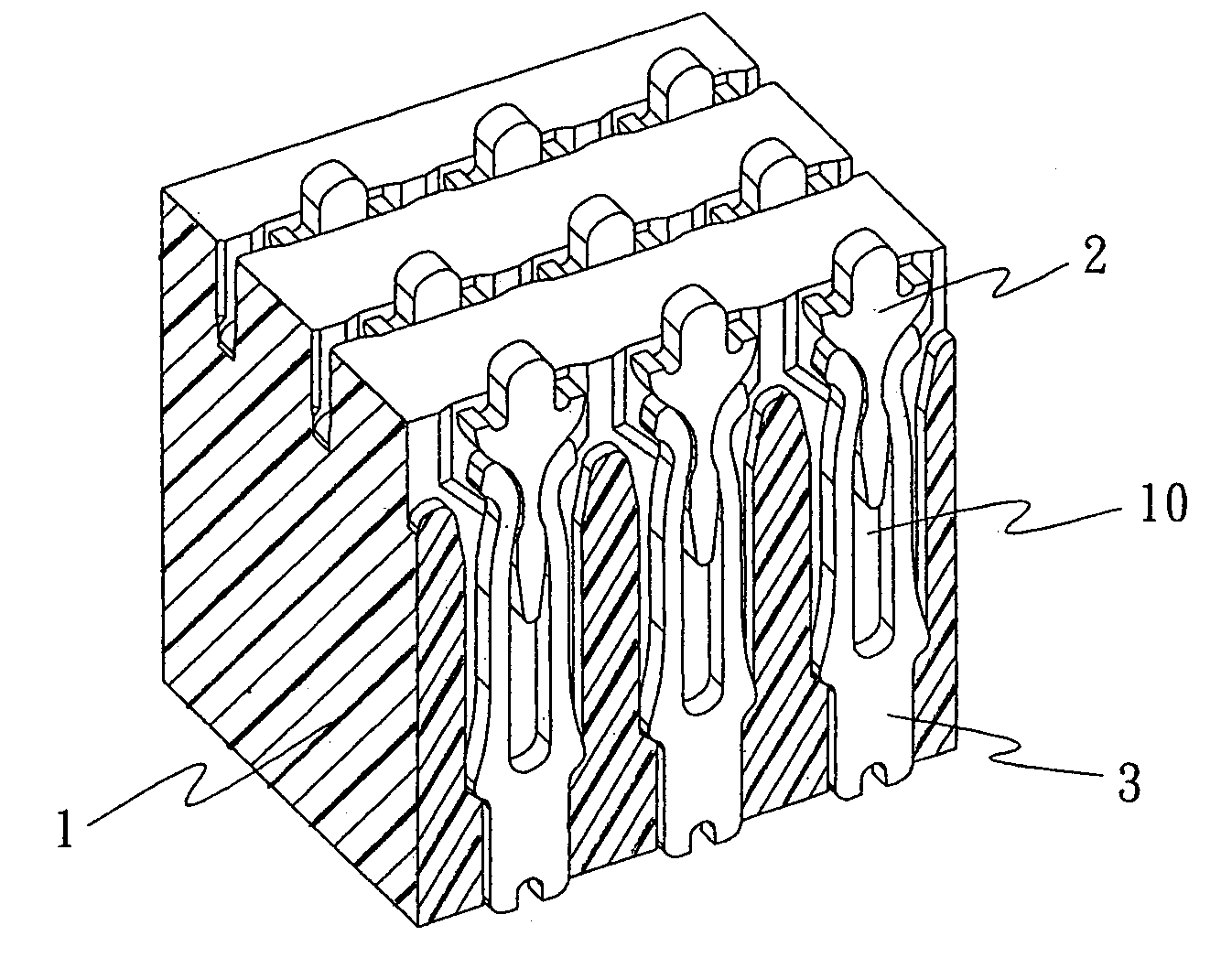
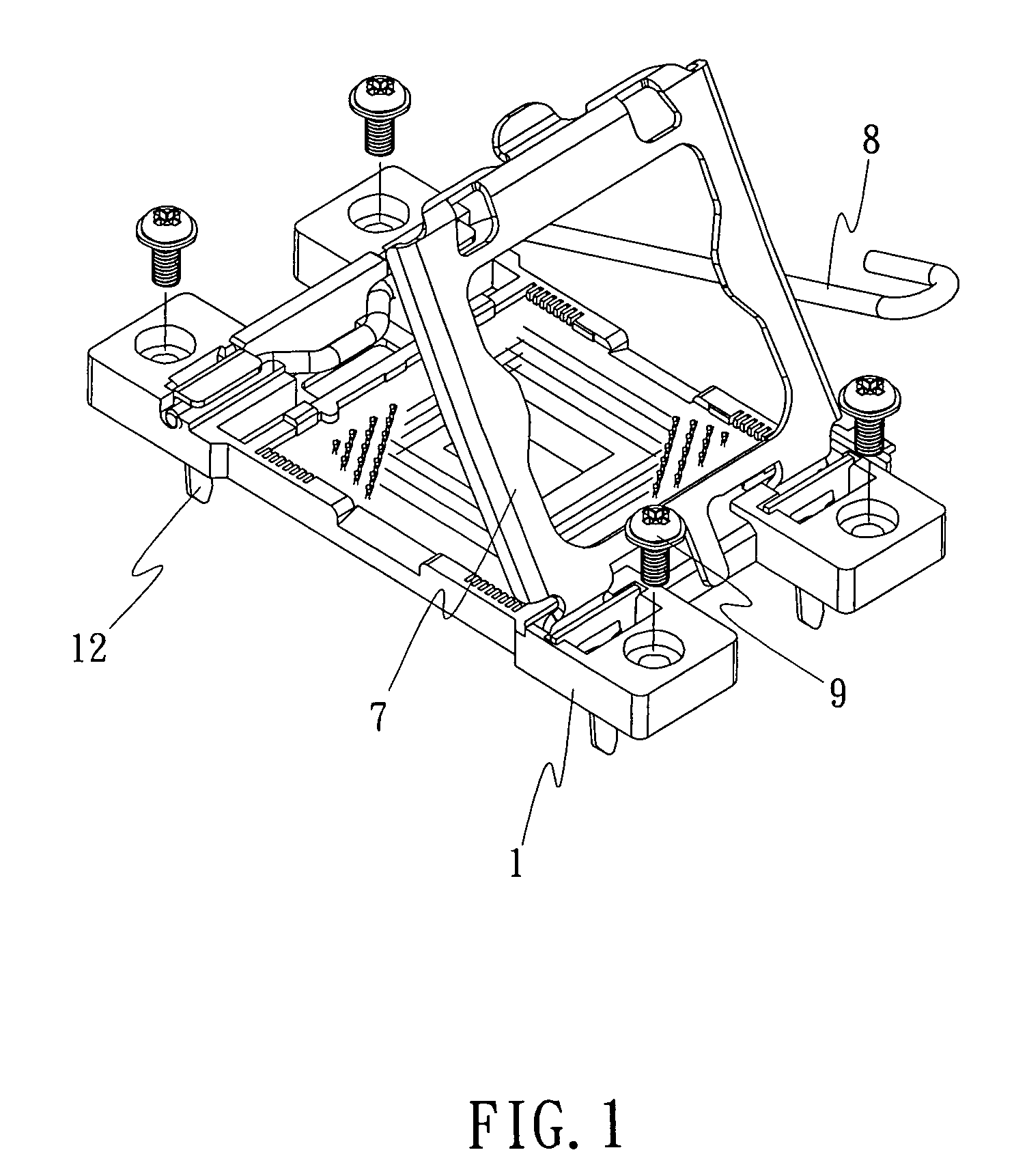
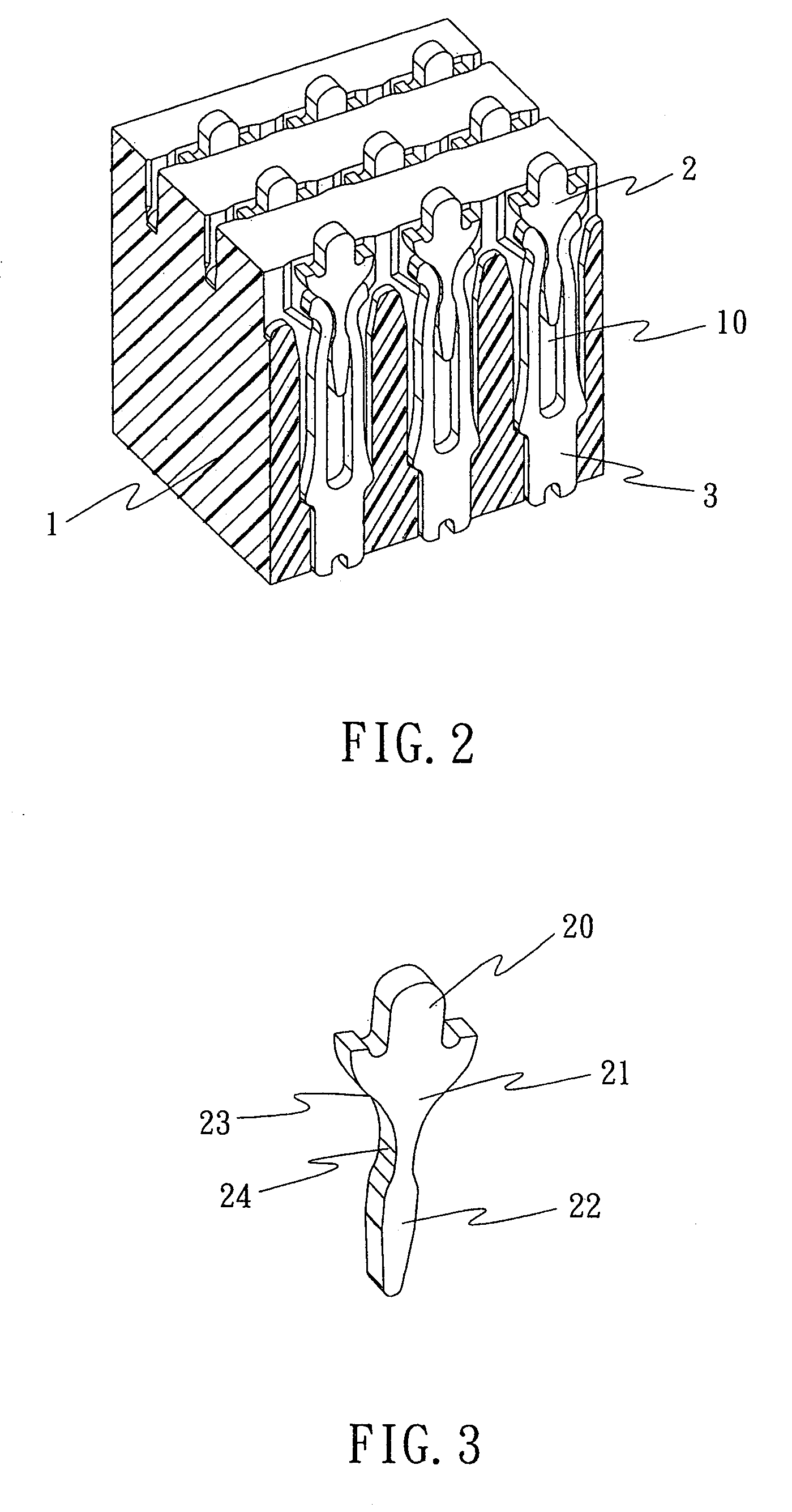
[0021]Please refer to FIGS. 1 through 7. The electrical connector of this invention comprises the insulator body 1 and the conductive terminal, one end is the top cover body 7 for pressing against the chip module, and installed on the other end of the insulator body is designed with a joystick 8 for pressing the top cover 7 to the insulator main body. On the four sides of the insulator body a connecting structure 9 is designed for connecting the electrical connector to PCB, where on the insulator body 1 is designed with several terminal receptor holes 10; each receptor hole 10 is designed with the interconnecting first conductive terminal 2 and the second conductive terminal 3; the two conductive terminal can move relative to each other; the said second conductive terminal 3 can be fitted into the receptor 10, the first conductive terminal 2 can be moved to connect to the second conductive terminal 3; the said first conductive terminal 2 and the second conductive terminal 3 can both...


PUM


Abstract

An electrical connector for a chip module including an insulator body and a conductive terminal. The insulator body has a plurality of receptor holes. Each of the plurality of receptor holes has a first conductive terminal and a second receptor hole. A first end of the first conductive terminal forms a first conductive connecting section connected to a terminal of the chip module and a second end forming a press-on section. A first end of the second conductive terminal forms a second conductive connecting section that could be electrically connected to an external electronic terminal and a second end forms an elastic section that presses against the press-on section of the first conductive terminal. At least one part of the first conductive connecting section is located at an oblique angle relative to an outer edge of the insulator body.

Description

BACKGROUND OF THE INVENTION[0001](a) Field of the Invention[0002]This invention is regarding the design of a kind of electrical connector, in particular a kind of electrical connector for the connection with the pressed on contact of chip module.[0003](b) Description of the Prior Art[0004]In the present market, there is a kind of LGA chip module available in some electronic products (such as PC). The conductive connection side of this kind of chip module is in the form of a washer. The electrical connector connecting to it is designed with a terminal in contact with a pressed on conductive terminal. The electrical connector of the present art includes the insulator body and conductive terminal. The insulator body is installed with a conductive terminal receptor for housing the conductive terminal. The holding part is formed in one body, including the holding part that is held in the main body. The holding part extending downward is designed with the soldering section to be soldered ...

Claims


Application Information

Patent Timeline
Patent Type & Authority Patents(United States)
IPC IPC(8): H01R12/00H01R12/57H01R12/71
CPCH01R13/2407H05K7/1069
Inventor JU, TEDCHANG, WEN-CHUNG
Owner LOTES
Why Eureka
Try Eureka