Forward-shielding blood collection set

a forward shielding and blood collection technology, applied in the field of blood collection sets, can solve the problems of repeated use of a relatively expensive holder, complex arrangements that are costly to manufacture and assemble, and expose the user to potential needle-stick wounds, so as to prevent inadvertent removal

Active Publication Date: 2007-04-10
BECTON DICKINSON & CO
View PDF27 Cites 65 Cited by
  • Summary
  • Abstract
  • Description
  • Claims
  • Application Information

AI Technical Summary

Benefits of technology

[0021]In a modification of the foregoing shielding needle assembly, the shielding needle assembly may further include a packaging shield disposed on a distal end of the hub and enclose the puncture tip of the needle cannula in the retracted position of the safety shield. The at least one release member may include a locking tab engaging a locking groove in the packaging shield to prevent inadvertent removal of the packaging shield. The hub and at least one release member may be further adapted such that application of radial pressure to the at least one release member causes the at least one release member to pivot radially inward and disengage the locking tab from the locking groove, thereby generally releasing the packaging shield from the hub, and further causing the at least one release member to engage the safety shield and maintain the safety shield in the retracted position. At least partial release or lessening of the radial pressure preferably allows the drive member to disengage the at least one release member from the safety shield and move the safety shield from the retracted position to the extended position.

Problems solved by technology

Thus, these blood collection devices allow repeated use of a relatively expensive holder upon replacement of relatively inexpensive medical needles and / or fluid collection tubes.
This results in complex arrangements that are costly to manufacture and assemble.
Additionally, operation of the needle assemblies to move the tip guard into the proper position over the pointed distal end of the needle cannula requires substantial manual manipulation by the user of the device, exposing the user to potential needle-stick wounds.

Method used


Image

  • Forward-shielding blood collection set
  • Forward-shielding blood collection set
  • Forward-shielding blood collection set

Examples


Embodiment Construction

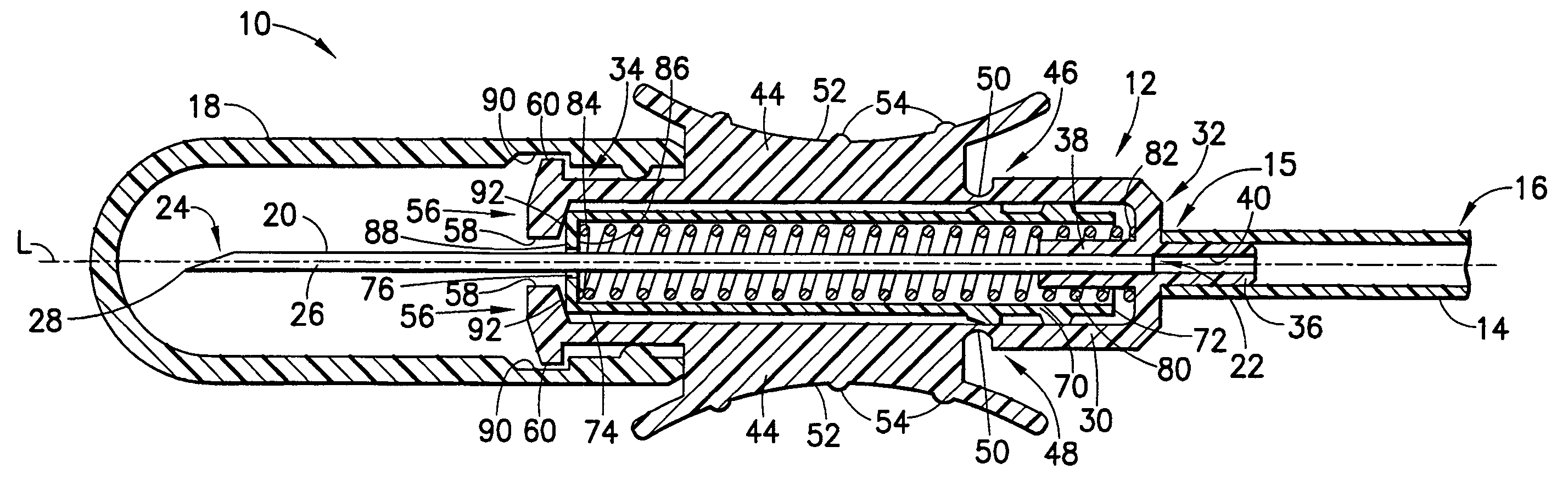
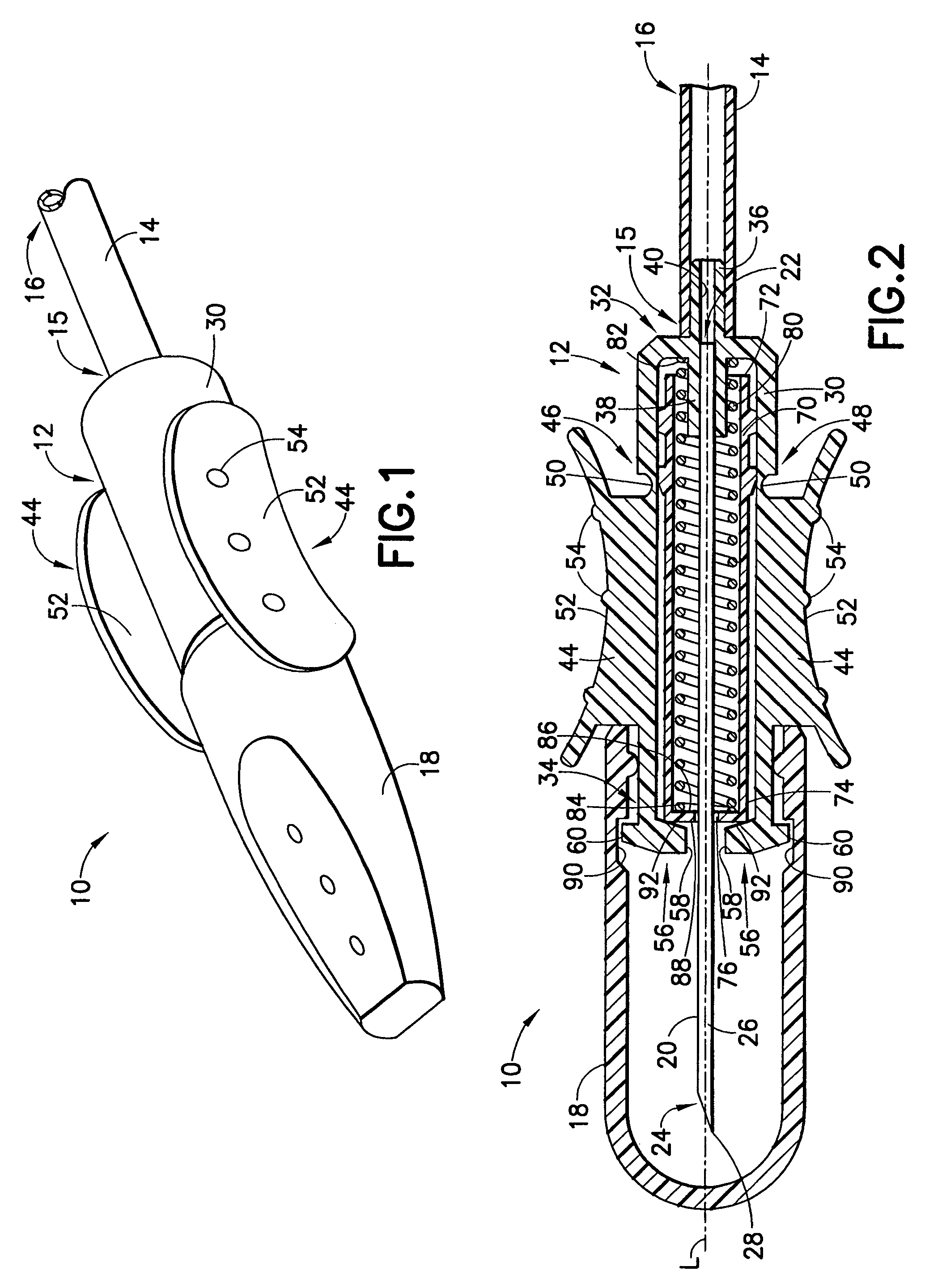
[0036]Referring to the drawings in which like reference characters refer to like parts throughout the several views thereof, FIG. 1 illustrates generally a blood collection set 10 in accordance with the present invention and its related features. The present invention is generally described in terms of a blood collection set, and encompasses such a blood collection set, as well as a shielding needle assembly for use in such a blood collection set.

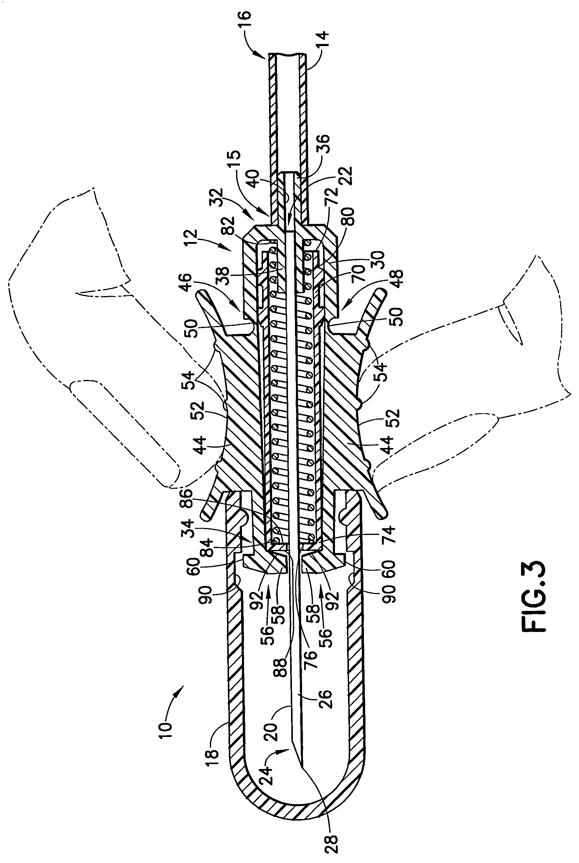
[0037]As shown generally in FIG. 1, the blood collection set 10 includes a shielding needle device or assembly 12, a flexible tube 14 extending from the needle device or assembly 12 and having first and second ends 15, 16, and a packaging cover or shield 18 removably mounted to the needle assembly 12 opposite tube 14, such as through a frictional engagement. The blood collection set 10 and shielding needle assembly 12 of the present invention are shown in greater detail in FIGS. 2–8, and generally include a needle cannula 20, a hub 30, a ne...


PUM


Abstract

A blood collection set includes a needle having a puncture tip, a hub supporting the needle and including a release member, a safety shield, a drive member, and a packaging shield disposed on the hub. The safety shield is movable from a retracted position within the hub to an extended position shielding the puncture tip of the needle. The packaging shield encloses the puncture tip of the needle in the retracted position of the safety shield. The shielding feature of the blood collection set is activated by applying radial pressure to the release member, causing the release member to release the packaging shield from the hub, and maintain the safety shield in the retracted position. Upon sufficient or partial release of radial pressure, the drive member disengages the release member from the safety shield and moves the safety shield from the retracted position to the extended positions.

Description

BACKGROUND OF THE INVENTION[0001]1. Field of the Invention[0002]The present invention relates to blood collection sets for safe and convenient handling of needles used in blood collection procedures. More particularly, the present invention relates to a blood collection set including a forward-shielding needle safety shield for protecting users from a used needle tip, and further including a packaging shield adapted to prevent premature actuation of the safety features of the blood collection set.[0003]2. Description of Related Art[0004]Disposable medical devices having medical needles are used for administering medication or withdrawing fluid from the body of a patient. Such disposable medical devices typically include blood collecting needles, fluid handling needles, and assemblies thereof. Current medical practice requires that fluid containers and needle assemblies used in such devices be inexpensive and readily disposable. Consequently, existing blood collection devices often e...

Claims


Application Information

Patent Timeline
Patent Type & Authority Patents(United States)
IPC IPC(8): A61M5/32
CPCA61M25/0631A61M25/0637A61M5/326A61M5/3204A61M5/321A61M5/3213
Inventor CRAWFORD, JAMIESON
Owner BECTON DICKINSON & CO
Why Eureka
Try Eureka