Method of installing circuit member in resin-molded panel

Active Publication Date: 2007-04-10
YAZAKI CORP
View PDF10 Cites 2 Cited by
  • Summary
  • Abstract
  • Description
  • Claims
  • Application Information

AI Technical Summary

Benefits of technology

[0047]In the invention, the receiving recess is formed in the base mold. This receiving recess is formed into a channel shape so as to receive the end portion of the circuit member. Thanks to the provision of this receiving recess, the processing of the end portion of the long circuit member at the time of molding can be effected easily.
[0048]In the invention, the holder portion is formed in the receiving recess. With this construction, the end portion, received in the receiving recess, is prevented from projecting outwardly therefrom. Therefore, the constant quality of the production configuration after the molding is achieved.
[0049]In the invention, the receiving recess is closed by the lid member. Therefore, even if the heated and softened panel material falls into the receiving recess without such a lid member, such falling is prevented by the lid member. Therefore, the constant

Problems solved by technology

Firstly, it is difficult to form small, fine claw-like projections, such as the retaining convex portions 5, by vacuum forming, and undercuts are formed at the retaining convex portions 5, respectively, and this invites a problem that the productivity is lowered.
Secondly, there is encountered a problem that with the small, fine claw-like projections such as the retaining convex portions 5, the holding and fixing of the circuit member 3 are not sufficient.
Thirdly, the

Method used


Image

  • Method of installing circuit member in resin-molded panel
  • Method of installing circuit member in resin-molded panel
  • Method of installing circuit member in resin-molded panel

Examples


Embodiment Construction

[0085]A preferred embodiment of the present invention will now be described with reference to the drawings.

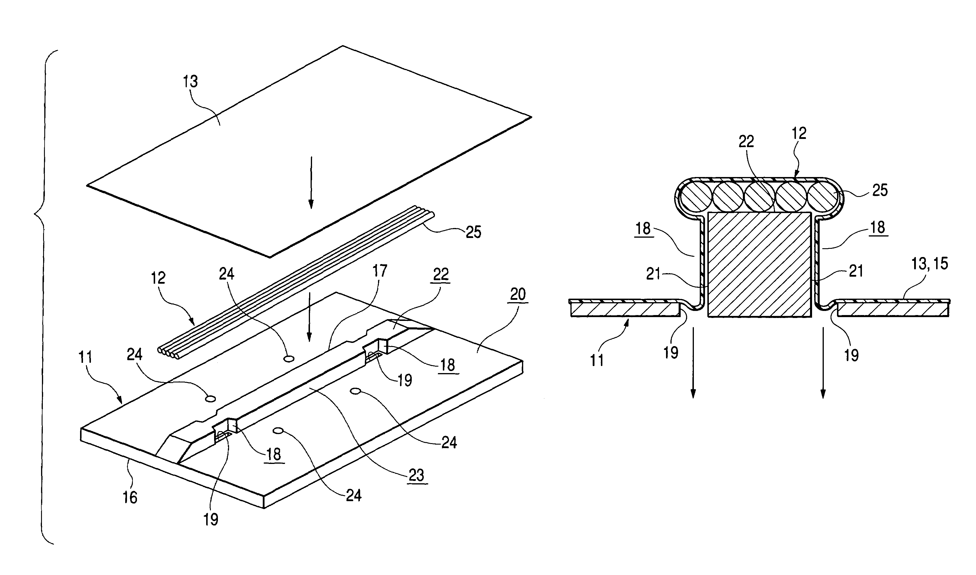
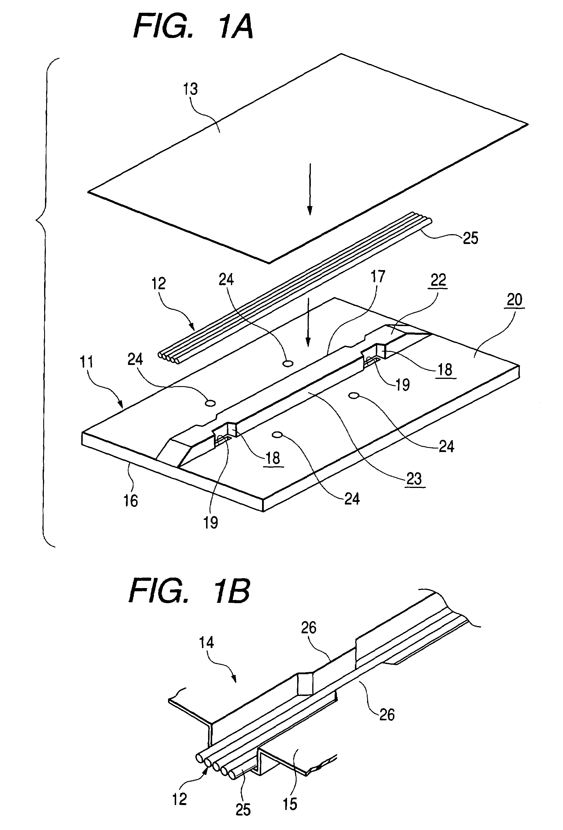
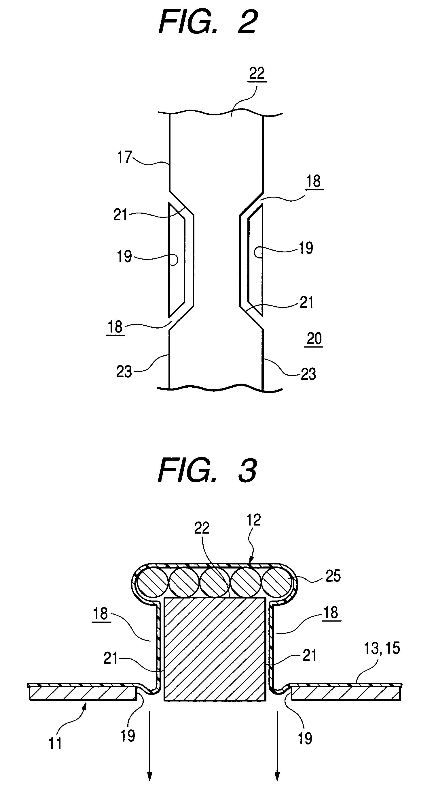
[0086]FIG. 1A is an exploded, perspective view explanatory of a method of installing a circuit member in a resin-molded panel, and FIG. 1B is a perspective view of a circuit member-incorporating resin-molded panel. FIG. 2 is a plan view of a circuit member-installing portion of a vacuum forming mold, FIG. 3 is a cross-sectional view of an important portion explanatory of the method of installing the circuit member in the resin-molded panel, and FIG. 4 is a cross-sectional view of an important portion of the circuit member-incorporating resin-molded panel. For better understanding, part of the drawings are exaggerated or omitted. First, the construction will be described.

[0087]In FIG. 1, reference numeral 1 denotes the vacuum forming mold of the invention, reference numeral 12 the circuit member, and reference numeral 13 a panel material. Reference numeral 14 denotes the circuit...


PUM

PropertyMeasurementUnit
Widthaaaaaaaaaa
Heightaaaaaaaaaa

Abstract

A method includes a first, a second and a third step, and a circuit member is installed in a resin-molded panel simultaneously when this resin-molded panel is vacuum formed. In the first step, the circuit member to be installed is placed on an upper surface of a circuit member-installing portion formed on and projecting from a front surface of a base mold. In the second step, a heated and softened panel material is laid on the front surface of the base mold. In the third step, the air between the panel material and the base mold is drawn via notch spaces and air-drawing holes.

Description

[0001]The present application is based on Japanese Patent Application Nos. 2002-124846 and 2003-013572, the entire contents of which are incorporated herein by reference.BACKGROUND OF THE INVENTION[0002]1. Field of the Invention[0003]This invention relates to a method of installing a circuit member in a resin-molded panel and also to a vacuum forming mold for installing the circuit member.[0004]2. Related Art[0005]Fastening members, such as clamps, have heretofore been used for mounting a wire harness (circuit member) on a panel of a vehicle such as an automobile, and these clamps have been fixedly secured to the panel to effect the mounting of the wire harness. There is also known a structure for fixing a wire harness, disclosed for example in Japanese Patent Publication No. JP H09-19035A.[0006]In recent years, various parts of an automobile have been modularized. There has been proposed a construction in which a wire harness is incorporated in a resin-molded panel. As such propose...

Claims


Application Information

Patent Timeline
IPC IPC(8): B29C51/10B29C51/12B29C51/16B29C51/36B29C51/30B29L31/34H02G3/04H02G3/30H02G3/38
CPCB29C51/12B29C51/16H02G3/305B29C51/10B29C51/30B29C51/40B29C2791/006B29L2031/3061
Inventor KISU, NAOMISOSHINO, EMI
Owner YAZAKI CORP
Why Eureka
Try Eureka