Method and apparatus for the mounting of and circumferential displacement of radial forces in a stator core assembly

a stator core and circumferential displacement technology, applied in the direction of dynamo-electric machines, supports/encloses/casings, magnetic circuit shapes/forms/constructions, etc., can solve problems such as impeded assembly

Active Publication Date: 2007-04-10
SIEMENS ENERGY INC
View PDF17 Cites 52 Cited by
  • Summary
  • Abstract
  • Description
  • Claims
  • Application Information

AI Technical Summary

Benefits of technology

[0009]With the foregoing in mind, methods and apparatuses consistent with the present invention facilitate the placement of laminations or donuts onto the keybars of the stator frame. Laminations need to be tightly fit onto keybars, however, the same need for tightness makes stacking laminations onto keybars particularly onerous. If the clearance between the hook in the lamination and the keybar is small, assembly becomes impeded. This is exacerbated when donuts, which are preassembled groups of laminations, are attempted to be stacked onto the keybars. The present invention provides for enlarged grooves that more easily accept the keybars. This makes stacking laminations, both individually and in donuts, less restrictive. The laminations or donuts are then held in position by the insertion of a wedge or wedges. The wedge may be inserted by a variety of techniques, and multiple wedges may be used in each groove.
[0010]With wedges being placed towards the outer edges of the lamination or donut, the forces transferred to the lamination or donut from the keybar are distributed in a more circumferential, rather than exclusively radial, direction. This creates a more solid fit between the laminations and the keybars, since the laminations are subject to circumferential forces during the operation of the stator generator.
[0012]In another embodiment the present invention provides for a generator assembly, which comprises a generator assembly frame and multiple stacked laminations which form a stator core. Multiple keybars secure the stator core to the generator assembly. The laminations that make up the stator core have grooves in them that align with the keybars and which hold the laminations to the keybars. When the laminations are in place, the grooves have a larger cross section than the keybars, thereby forming gaps between the keybars and the laminations. In these gaps are multiple wedges, which ultimately allow for the secure fit of the stator core to the keybars.

Problems solved by technology

If the clearance between the hook in the lamination and the keybar is small, assembly becomes impeded.

Method used


Image

  • Method and apparatus for the mounting of and circumferential displacement of radial forces in a stator core assembly
  • Method and apparatus for the mounting of and circumferential displacement of radial forces in a stator core assembly
  • Method and apparatus for the mounting of and circumferential displacement of radial forces in a stator core assembly

Examples


Embodiment Construction

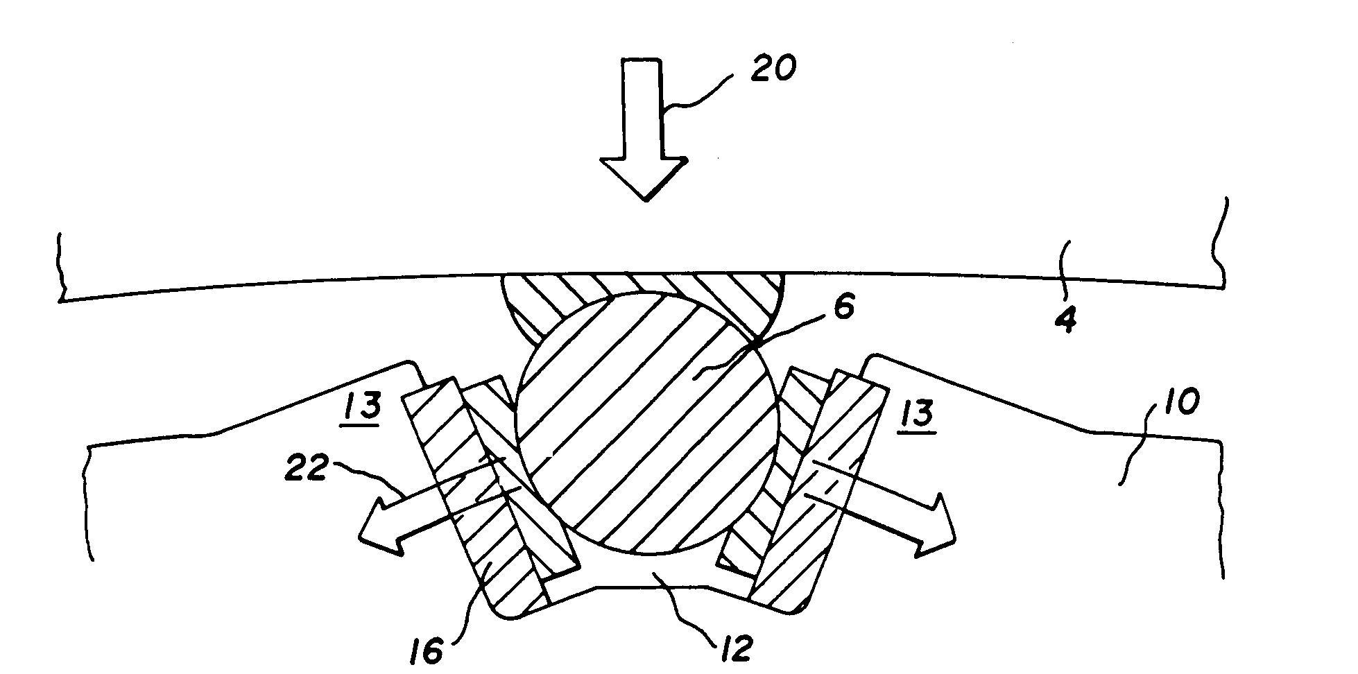
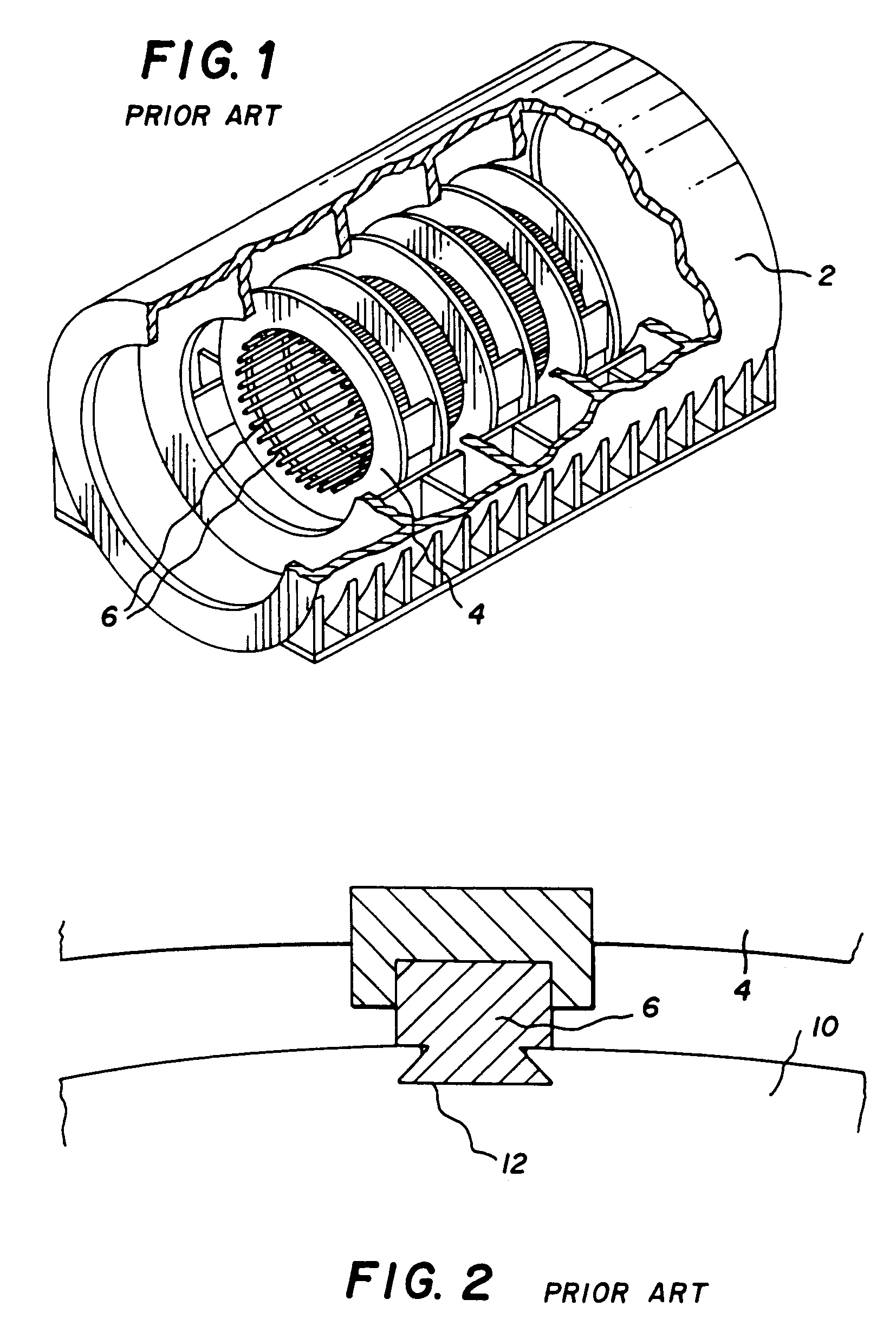
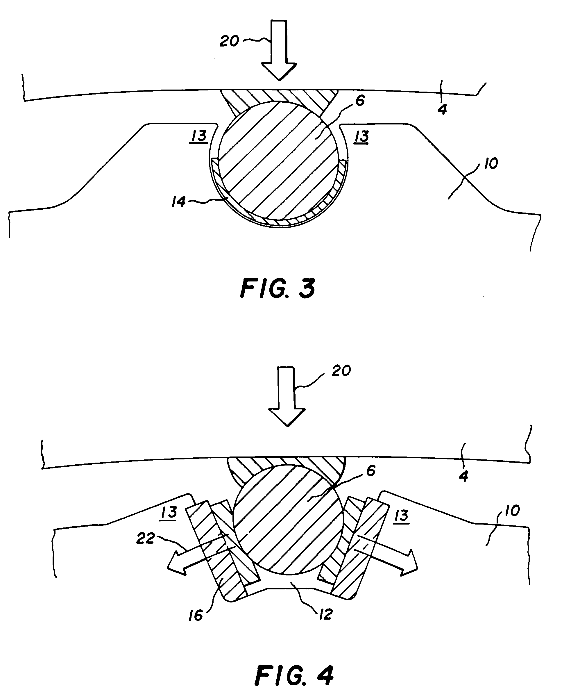
[0021]The present invention comprises a method of mounting laminations, either individually or in aggregate, onto stator frame keybars. Laminations have grooves along their outer length to accommodate the keybars. In the prior art the grooves have had to be to be closely fit on the keybars, which has permitted subsequent tightening of the guard rings around the stator core, since a loose fit between the keybars and laminations will cause damage to the stator core as well as produce excess noise and vibration. However, the very same tight-fit that is needed when the stator core is operating creates problems when mounting laminations onto the keybars and essentially precludes the assembly of large preassembled donuts, since lamination aggregates such as donuts have to fit onto multiple keybars simultaneously.

[0022]A trend in stacking the laminations has been to first compile the laminations into donuts before mounting them onto the keybars. This, however, further complicates the task ...


PUM


Abstract

The present invention facilitates the placement of laminations 10 onto keybars 6 of stator generators frames 2. Laminations need to be tightly fit onto keybars 6, however, the same need for tightness makes stacking laminations onto keybars particularly onerous. This is magnified when donuts, which are preassembled groups of laminations, are attempted to be stacked onto the keybars 6. The present invention provides for enlarged grooves 12 that more easily accept the keybars. This makes stacking laminations, both individually and in donuts, much easier. The laminations are then held in position by the insertion of a wedge 16. The wedge may be placed to disperse forces 20 transferred to the laminations in a circumferential manner 22.

Description

CROSS-REFERENCE TO RELATED APPLICATIONS[0001]This invention claims priority to U.S. Provisional application 60 / 565,307 filed on Apr. 26, 2004 entitled Methods and Apparatuses for Assembling Generator Stator Cores, which is incorporated herein by reference. This invention is further related to US applications: Apparatus and Method for the Installation of a Pre-Assembled Stator Core, by Allen, et al.; Horizontal Assembly of Stator Core using Keybar Extensions, by Sargeant et al.; Horizontal Assembly of Stator Core using a Central Rail Structure by Majernik et al.; all filed herewith and all incorporated herein by reference.FIELD OF THE INVENTION[0002]The present invention relates to power generators and more specifically, the assembly of the generator stator core.BACKGROUND[0003]The generator stator core is the largest monobloc component in the train of a turbine generator set. The stator cores are manufactured from thousands of thin steel laminations of which are stacked, pressed and...

Claims


Application Information

Patent Timeline
Patent Type & Authority Patents(United States)
IPC IPC(8): H02K1/12H02K1/18H02K15/02
CPCH02K1/185H02K15/028
Inventor SARGEANT, JOHN BARRYCHRISTODOULOU, ALEX
Owner SIEMENS ENERGY INC
Why Eureka
Try Eureka