Resistive probe tips

a technology of resistive probe tips and resistive tips, which is applied in the direction of electrical testing, measurement devices, instruments, etc., can solve the problems of reducing the bandwidth performance of the tip, and achieve the effect of flat frequency response and bandwidth loss

Active Publication Date: 2007-04-10
TELEDYNE LECROY
View PDF19 Cites 9 Cited by
  • Summary
  • Abstract
  • Description
  • Claims
  • Application Information

AI Technical Summary

Benefits of technology

[0012]A probe tip of the present invention has substantially flat frequency response without a loss of bandwidth. Further, probe tips made from the resistive material may be used as “touch and browse” probing tips.

Problems solved by technology

In use, this type of probe tip usually must be soldered into place, as its leads are too soft for a browsing (quick touch) type of probing of electrical components.
As shown in trace D of FIG. 1, although this would bring down the peak of the frequency response, it would also reduce the bandwidth performance of the tip.

Method used


Image

  • Resistive probe tips
  • Resistive probe tips
  • Resistive probe tips

Examples


Embodiment Construction

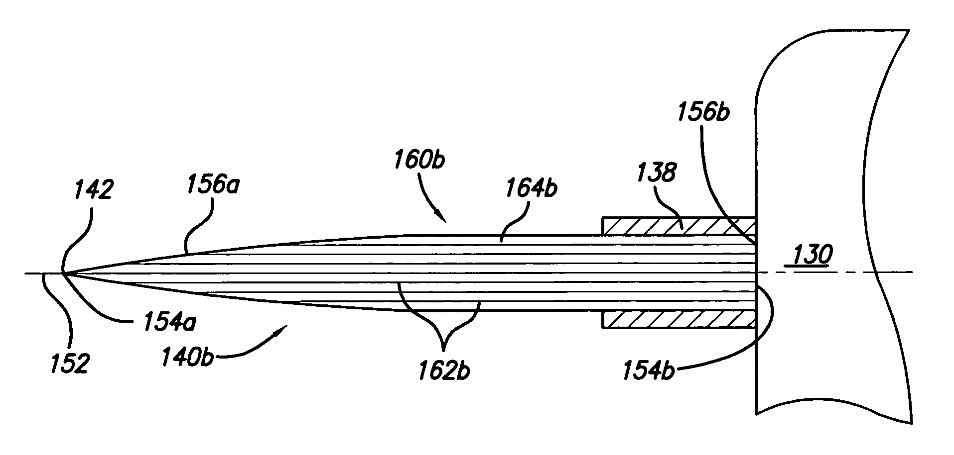
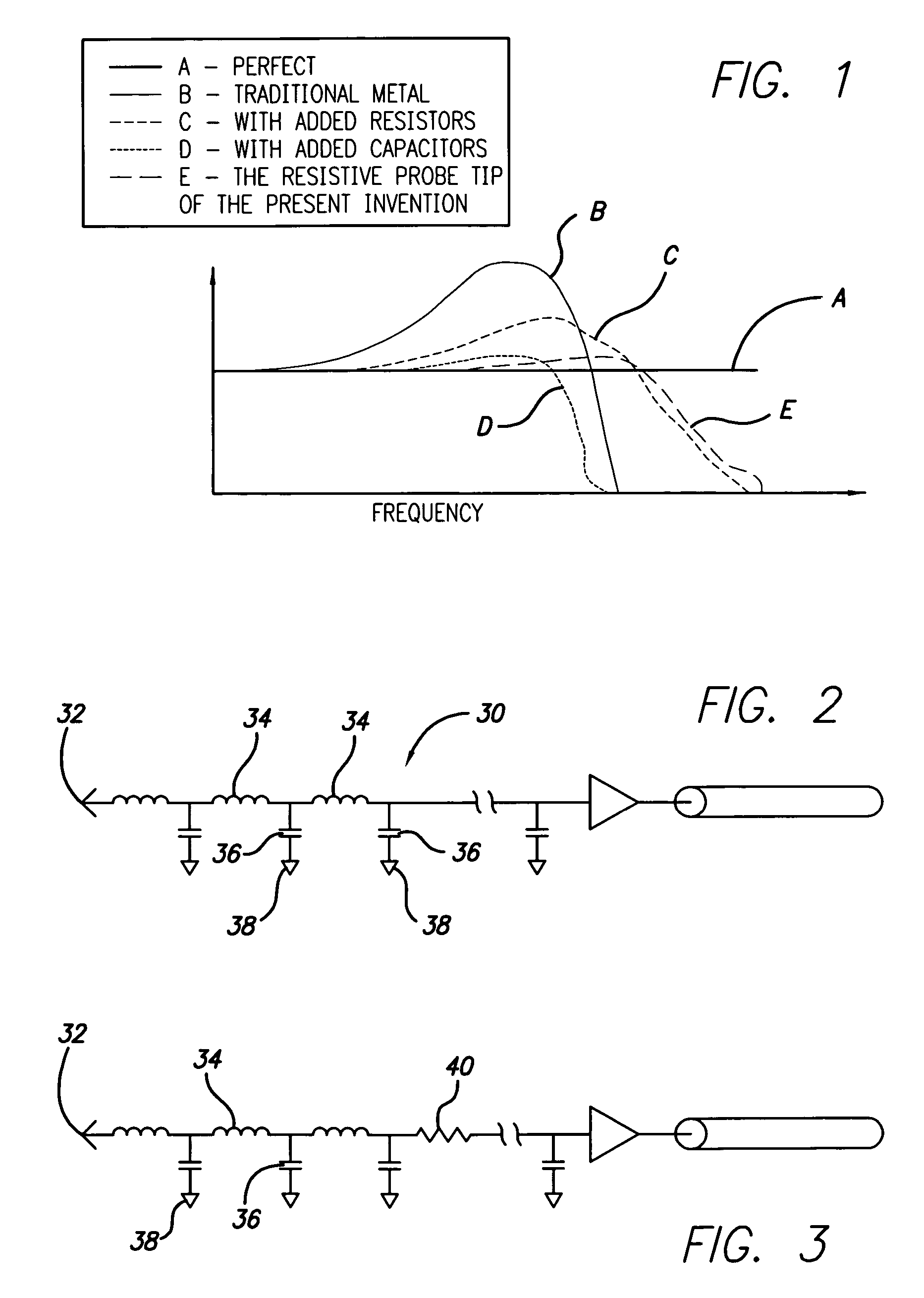
[0029]The present invention is a resistive test probe tip in which the entire tip (or substantially the entire tip) is a resistor. In one preferred embodiment, the tip is made from resistive material. As can be seen in FIG. 1, the present invention has a frequency response such as trace E that is a significant improvement over the frequency response (trace B) of a traditional metal test probe tip (FIG. 2) and to frequency responses (trace D) of test probe tips with at least one added capacitor. The frequency response (trace E) of the present invention is similar (and preferably slightly improved) to frequency responses (trace C) of test probe tips with at least one added resistor (FIG. 3). Because the entire extension is resistive, the resistive test probe tip of the present invention may be a long probing tip without the problems associated with length and the increased inductance usually associated with length. In addition, because of the strength of the probing tips of the presen...


PUM


Abstract

A test probe tip constructed substantially from resistive material. The resistive material is made of resistive conducting material substantially enclosed in and dispersed throughout encapsulating material. The test probe has a probing end for probing electronic circuitry and a connection end for interfacing with a probing head. The resistive conducting material forms at least one path through the encapsulating material from the probing end to the connection end. The resistive conducting material may be a plurality of longitudinally extending resistive / conductive members or a plurality of particulate resistive / conductive members.

Description

[0001]The present application is an application claiming the benefit under 35 USC Section 119(e) of U.S. Provisional Patent Application Ser. No. 60 / 531,076 filed Dec. 18, 2003. The present application is based on and claims priority from this application, the disclosure of which is hereby expressly incorporated herein by reference in its entirety.BACKGROUND OF INVENTION[0002]The present invention is directed to electrical test probe tips and, more particularly to resistive test probe tips.[0003]Electrical test probes are used to provide an electrical connection between electrical components and testing instruments such as oscilloscopes and other measuring, monitoring, diagnostic, and signal processing instruments. An electrical test probe generally consists of a probing head, a cable, and a testing instrument connector. The probing head may have an integral or replaceable electrical test probe tip that is suitable for making an electrical contact with electrical components. The test...

Claims


Application Information

Patent Timeline
Patent Type & Authority Patents(United States)
IPC IPC(8): G01R31/02G01R1/067
CPCG01R1/06711G01R1/06755G01R1/06772G01R1/06788
Inventor CAMPBELL, JULIE A.JACOBS, LAWRENCE W.
Owner TELEDYNE LECROY
Why Eureka
Try Eureka