Distortionless sound playback system for counter electromotive force signals

A back electromotive force, distortion-free technology, applied in the direction of electrical components, transducer circuits, sensors, etc., can solve problems such as blindness and failure to meet expectations, and achieve the effect of no distortion of sound, wide frequency response, and distortion elimination

Inactive Publication Date: 2012-11-28
方炳钧
View PDF0 Cites 2 Cited by
  • Summary
  • Abstract
  • Description
  • Claims
  • Application Information

AI Technical Summary

Problems solved by technology

However, whether it is a "dynamic feedback system" or a "dynamic feedback speaker", they are all implemented with the concept of adding a microphone. Influence, in fact, always fail to achieve the expected results
For this reason, until now, there is no such system or speaker on the market at all, which is a great pity!

Method used


Image

  • Distortionless sound playback system for counter electromotive force signals
  • Distortionless sound playback system for counter electromotive force signals
  • Distortionless sound playback system for counter electromotive force signals

Examples


Embodiment 1

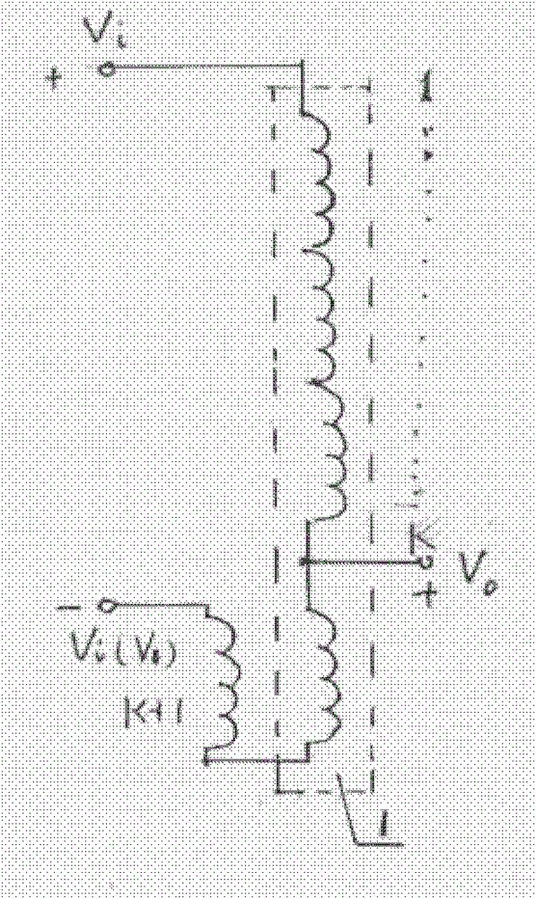
[0027] refer to figure 2 , regard the speaker voice coil as (K+1) segments with the same effective length, starting from the hot end of the voice coil (end with the same name) as the first segment, until K-1, K, K+1 segment and then to the cold end of the voice coil (not the end of the same name) ends. A tap is drawn between the K-1 section and the K section as the output terminal. For conventional loudspeakers, the output terminal (between the cold terminal of the voice coil) should get Uo=2E+2I(ZL+R), where E, ZL, R are the parameters of a coil, and I is the voice coil current.

[0028] The counter electromotive force signal speaker makes two changes: firstly, the K+1 section is separated from the moving voice coil, and placed in the magnetically conductive soft iron in the speaker, that is to say, the K+1 section does not participate in the movement of the voice coil. Uo=E+2I(Z L +R), minus one E. Then reverse it again, according to the self-inductance principle K, IZ ...

Embodiment 2

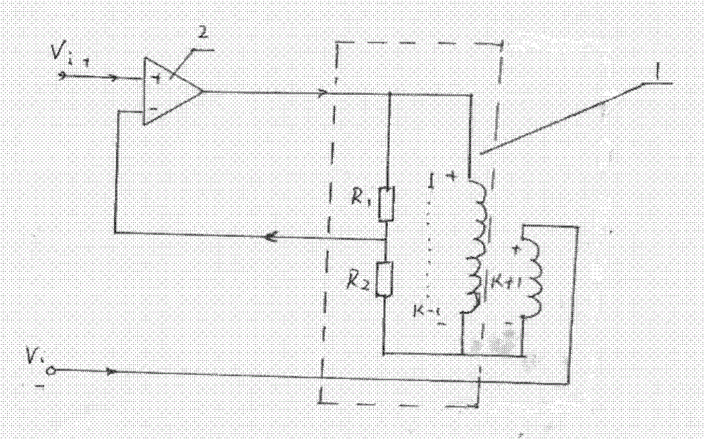
[0030] refer to image 3 , use two resistors R1, R2 to make the total Uo value as a partial pressure of K / 1 to replace the movable K section in the first embodiment to obtain Uo=E+I(Z L +R), and after canceling the K section in the voice coil, the K-1, K+1 sections are connected and the tap is taken out, and the negative I(Z L +R), and then E+I(Z L +R) mixed and added, just offset I(Z L +R) item, the remaining counter electromotive force E signal is output to the counter electromotive force signal amplifier. This method is simpler than the first embodiment, but the disadvantage is that the adjustment of the voltage dividing resistor needs to be precise.

Embodiment 3

[0032] refer to Figure 4, the speaker voice coil is divided into two groups in parallel (actual speaker voice coils are often double-wired in parallel), the two groups are from the first segment to the K segment, the two groups of winding directions are exactly the same, each group K-1 , the output lines are drawn between the two sections of K. For conventional speakers, the voltage values ​​of the two output lines (between the cold end of the voice coil) are obtained: Uo=E+I(Z L +R).

[0033] Only one change is made to the back EMF signal speaker: the K segment of one group is changed to be fixed in the magnetically conductive soft iron inside the speaker, and does not participate in the movement of the voice coil. At this time, the voltages obtained on the two sets of output lines are respectively U1=E+I(Z L +R) and U2=I(Z L +R), at this time, U1 and U2 are sent to the back electromotive force signal amplifier to subtract them to obtain the back electromotive force E sig...


PUM


Abstract

The invention discloses a distortionless sound playback system for counter electromotive force signals. The distortionless sound playback system is characterized by comprising a counter electromotive force signal loudspeaker and a counter electromotive force signal amplifier, wherein when the loudspeaker body is distorted, and the motion speed of a paper disk is deviated from a desired value under the pressure of air in a sound box or the influence of sound reflection, resonance, standing waves and harmonic factors, a sound coil in the counter electromotive force signal loudspeaker, which is connected with the paper disk, can instantly detect the generated deviation and feed back the deviation to the counter electromotive force signal amplifier; and the counter electromotive force signal amplifier instantly makes a response to rectify the deviation until the deviation completely disappears. The distortionless sound playback system is rational in design; the loudspeaker is changed into a standard four-end network provided with an input and an output; and moreover, an output signal can really reflect an electric signal of the motion of the loudspeaker, so that a power amplifier and the loudspeaker belong to a real electronic network system. The frequency response is wide and flat, and the sound is not subjected to distortion and phase shift; the counter electromotive force signal loudspeaker can replace all treble, alto and bass loudspeakers in the sound box; and therefore, the step of adjusting the troublesome frequency divider is omitted, and the manufacturing cost of the sound box is greatly reduced.

Description

technical field [0001] The invention relates to a sound system, in particular to a back electromotive force signal distortion-free sound reproduction system. Background technique [0002] The current audio playback system consists of three parts: the front stage, the rear stage and the speaker, and the front stage and the rear stage are often combined together, called a combination machine, regardless of whether the front stage and the rear stage are combined or not, and the speaker is always independent. of. Manufacturers of audio power amplifiers care about the power, distortion, frequency response and other indicators of the amplifier, but pay less attention to whether the speaker is working well or not. [0003] Although amplifiers and speakers are called a sound system, they are not a true electronic network system. It is not difficult to see that the output of the power amplifier is connected to the speaker through a pair of wires, and the speaker produces sound due ...

Claims


Application Information

Patent Timeline
IPC IPC(8): H04R3/00
Inventor 方炳钧
Owner 方炳钧
Why Eureka
Try Eureka