
Adaptive impedance transformer of transistor

An impedance converter and self-adaptive technology, applied in the field of electronics, can solve the problems of low power factor, small frequency response range, large reactive power loss, etc., and achieve the effect of high power factor, wide matching range and good matching.

Inactive Publication Date: 2005-04-27
常德胜
View PDF0 Cites 0 Cited by
  • Summary
  • Abstract
  • Description
  • Claims
  • Application Information

AI Technical Summary

Problems solved by technology

As we all know, the use of transformers for impedance matching has many shortcomings such as large volume, large power consumption, and narrow matching frequency range.
On November 22, 2000, the China Patent Office authorized and announced a utility model patent for a "low-power electronic impedance converter". The technical solution disclosed in the utility model patent is essentially a two-stage electronic amplifier. The ratio of the bias resistance and the feedback resistance is related, and the components used are all linear components. For inductive loads such as speakers and amplifying high-power audio signals, there are still the following deficiencies: 1. Low power factor and large reactive power loss: 2. Drive low-impedance inductive loads with serious mismatch; 3. Small frequency response range, serious distortion, and poor sound quality

Method used


Image

  • Adaptive impedance transformer of transistor
  • Adaptive impedance transformer of transistor

Examples


example 1

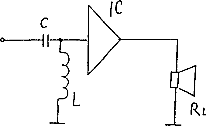
[0015] see figure 1 , the choice of the reactance of the inductance described in the present invention should be appropriate, if it is too small, the signal loss will be large, and generally 1-100H is suitable.

[0016] see figure 1 , the IC in this embodiment is a commercially available common audio power amplifier integrated block, and the coupling capacitance C connected in series at the input end of the IC is 10-150 microfarads, R L It is a 4 ohm electric speaker.

example 2

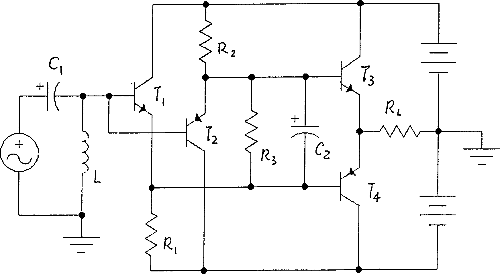
[0018] see figure 2 In this embodiment, the single-ended input audio power amplifier is composed of a fully symmetrical parallel voltage follower, the triodes T1 and T3 form a voltage follower, and the triodes T2 and T4 form another voltage follower. The audio signal transmitted by the coupling capacitor C1 is sent to the bases of the triodes T1 and T2. Since the inductance L is connected across the bases of the triodes T1 and T2 to the ground, a true zero-point feed is achieved; if the signal is The positive polarity is amplified by the transistor T1 and coupled to the transistor T3 by the resistor R3 and the capacitor C2 to drive the speaker R L , if the signal is negative, it is amplified by the transistor T2 and coupled to the transistor T4 by the resistor R3 and the capacitor C2 to drive the speaker R L . The values ​​of the capacitor C1 and the inductor L in this embodiment can be implemented with reference to Example 1.

[0019] With the 30W power amplifier produced...


PUM


Abstract

The present invention discloses one kind of adaptive transistor impedance converter. The impedance converter includes single-end input audio power amplifier and features that the single-end input audio power amplifier has one input pulldown inductor connected to ground. The power amplifier made based on the technology of the present invention may be matched freely with electrically driven loudspeaker of 1-16 ohm impedance to produce clear and vigorous high quality sound.

Description

Technical field: [0001] The invention relates to the field of electronic technology, and relates to an impedance conversion device, in particular to a transistor impedance converter, which is suitable for final stage amplification of audio signals. Background technique: [0002] The final load of audio equipment generally uses speakers. Since the AC impedance of the speakers is low and changes with the frequency of the input signal, it is difficult for ordinary transistor amplifiers to meet the requirements. In order to obtain effective and appropriate power for the load, transformers are used in common circuits for impedance matching. As we all know, the use of transformers for impedance matching has many shortcomings such as large volume, large power consumption, and narrow matching frequency range. On November 22, 2000, the China Patent Office authorized and announced a utility model patent for a "low-power electronic impedance converter". The technical solution disclose...

Claims


Application Information

Patent Timeline
Patent Type & Authority Applications(China)
IPC IPC(8): H03F1/56
Inventor 常德胜
Owner 常德胜
Learn More