2:2 and 3:2 pull-down detection techniques

a detection technique and pull-down field technology, applied in the field of video signal processing, can solve the problems of generating a clearly visible loss of vertical resolution for relatively static images, prone to false detection of 2:2 pull-down field patterns, and high objectionable artifacts

Active Publication Date: 2007-04-10
CSR TECH INC
View PDF8 Cites 21 Cited by
  • Summary
  • Abstract
  • Description
  • Claims
  • Application Information

AI Technical Summary

Problems solved by technology

The merging technique is well suited for relatively static images, but produces highly objectionable artifacts when significant motion is present in the image.
The interpolation technique is well suited for video with high motion content, but produces a clearly visible loss of vertical resolution for relatively static images.
One problem with the 2:2 pull-down field motion detector circuit is that sometimes the 2:2 pull-down field motion detector circuit falsely detects a 2:2 pull-down field pattern.
As such, more complex comparison techniques (e.g., techniques that use vertical high pass filters to compare the high frequencies within the consecutive fields) are used to compare the consecutive fields and thus generate the comparison values.
Unfortunately, these comparison techniques are susceptible to falsely detecting a 2:2 pull-down field pattern.
This is undesirable since the deinterlacer circuit merges the consecutive fields in the interlaced video signal when a 2:2 pull-down field pattern is falsely detected.
Since the consecutive fields in the interlaced video signal are from different points in time and are merged, highly objectionable artifacts (i.e., feathering or combing) appear in the displayed image.
Unfortunately, conventional video deinterlacers cannot detect the bad edit until comparison value CV16 is generated.
After comparison value CV11, this causes fields from different points in time to be merged together when generating the progressive video signal and thus ultimately results in an image that includes highly objectionable artifacts (i.e., feathering or combing).
A disadvantage with such look-ahead techniques is that they require up to six fields to be simultaneously stored in memory to detect bad edits.
This requires a large amount of memory, which is expensive from both an implementation and a production standpoint and thus is undesirable.
However, 3:2 pull-down field motion detector circuits are problematic since often times they do not correctly detect when an interlaced video signal was generated using 3:2 pull-down.

Method used


Image

  • 2:2 and 3:2 pull-down detection techniques
  • 2:2 and 3:2 pull-down detection techniques
  • 2:2 and 3:2 pull-down detection techniques

Examples


Embodiment Construction

[0110]Certain embodiments of the present invention and their advantages are best understood by referring to the drawings. Like reference numerals are used for like and corresponding parts of the various drawings.

I. Video Deinterlacer System With Improved 2:2 Pull-Down Detection

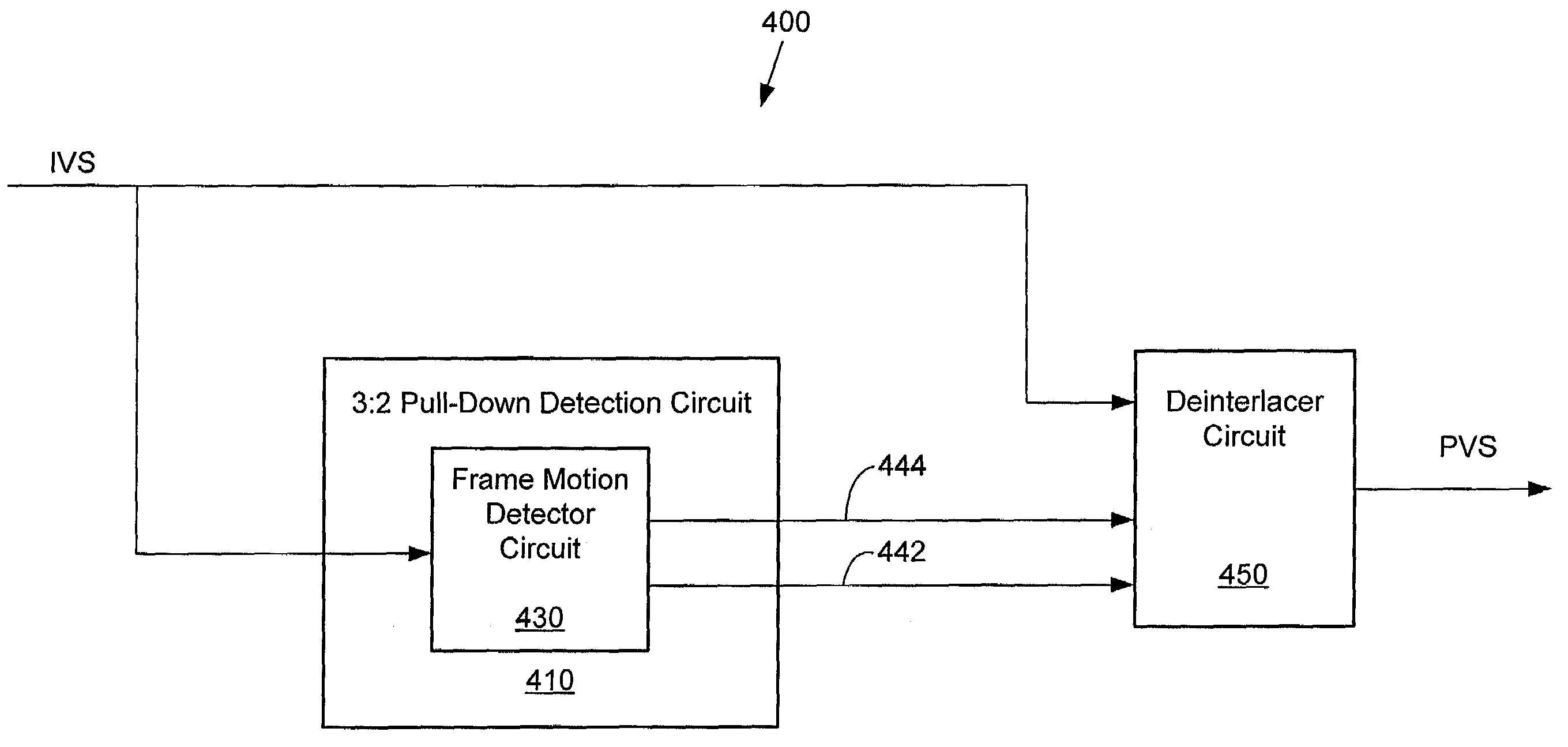
[0111]FIG. 3 is a block diagram of a video deinterlacer system 300, according to some embodiments of the present invention. Video deinterlacer system 300 includes a 2:2 pull-down detection circuit 310 and a deinterlacer circuit 350. 2:2 pull-down detection circuit 310 includes a field motion detector circuit 320, a frame motion detector circuit 330, and a control circuit 340. The functions performed by video deinterlacer system 300 can be implemented using hardware, firmware / microcode, software, or any combination thereof. Video deinterlacer system 300 can also be implemented on a single integrated circuit device or on multiple integrated circuit devices.

[0112]2:2 pull-down field motion detector circuit 320, w...


PUM


Abstract

Improved 2:2 and 3:2 pull-down detection techniques are presented. These techniques can, for example, be used when converting an interlaced video signal into a progressive video signal. The improved techniques are less susceptible to bad edits. In one embodiment, comparison values are generated using consecutive fields of the interlaced video signal having the same parity, with a sequence of one small comparison value followed four large comparison values, where the four large comparison values include two pairs of similar large comparison values, is used to indicate a 3:2 pull-down.

Description

BACKGROUND[0001]1. Field of the Invention[0002]The present invention relates to video signal processing and, more particularly, to improved 2:2 and 3:2 pull-down detection techniques. The techniques of the present invention can, for example, be used when converting an interlaced video signal into a progressive video signal.[0003]2. Related Art[0004]There are two common types of video display systems: interlaced display systems and progressive display systems. Interlaced display systems use interlaced video signals. An interlaced video signal includes even fields, which contain one half of the total lines displayed on a display, and odd fields, which contain the other half of the total lines displayed on the display. The even fields and the odd fields of the interlaced video signal are alternately scanned onto the display to generate an image. By contrast, progressive display systems use progressive video signals. A progressive video signal includes frames, each of which contains all...

Claims


Application Information

Patent Timeline
Patent Type & Authority Patents(United States)
IPC IPC(8): H04N7/01H04N5/44
CPCH04N7/0115H04N7/012
Inventor CHOW, WING-CHI
Owner CSR TECH INC
Why Eureka
Try Eureka