Tandem image forming device having a side-by-side arrangement of image forming sections

a technology of image forming and side-by-side arrangement, which is applied in the direction of corona discharge, thin material processing, instruments, etc., can solve the problems of irregular image density, inability to smoothly circulate or uniformly mix in the agitating section, and increase the overall size of the apparatus, so as to prevent a developer, avoid irregular image density, and promote smooth circulation of the developer

Inactive Publication Date: 2007-04-10
RICOH KK
View PDF38 Cites 28 Cited by
  • Summary
  • Abstract
  • Description
  • Claims
  • Application Information

AI Technical Summary

Benefits of technology

[0008]It is a first object of the present invention to provide a small size, tandem image forming device capable of preventing a developer from accumulating on a sleeve, promoting smooth circulation of the developer to thereby obviate irregular image density, and reducing a distance between nearby image forming means, and an image forming apparatus including the same and transferring images from the image forming device to a recording medium by way of an intermediate image transfer body.
[0009]It is a second object of the present invention to provide an image forming apparatus whose tandem image forming device is reduced in length to thereby further reduce the overall size of the apparatus.
[0010]It is a third object of the present invention to further reduce the overall size of an image forming apparatus by locating a cleaning device assigned to an intermediate image transfer body at a unique position.

Problems solved by technology

This kind of apparatus, however, has a problem that the distance between nearby image forming means and therefore the overall size of the apparatus increases.
Moreover, after development, the developer accumulated on the sleeve must be returned to the agitating section against gravity and therefore cannot be smoothly circulated or uniformly mixed in the agitating section.
Consequently, when the same image pattern is repeatedly output, the consumption of the toner differs from one position to another position, resulting in irregular image density.

Method used


Image

  • Tandem image forming device having a side-by-side arrangement of image forming sections
  • Tandem image forming device having a side-by-side arrangement of image forming sections
  • Tandem image forming device having a side-by-side arrangement of image forming sections

Examples


Embodiment Construction

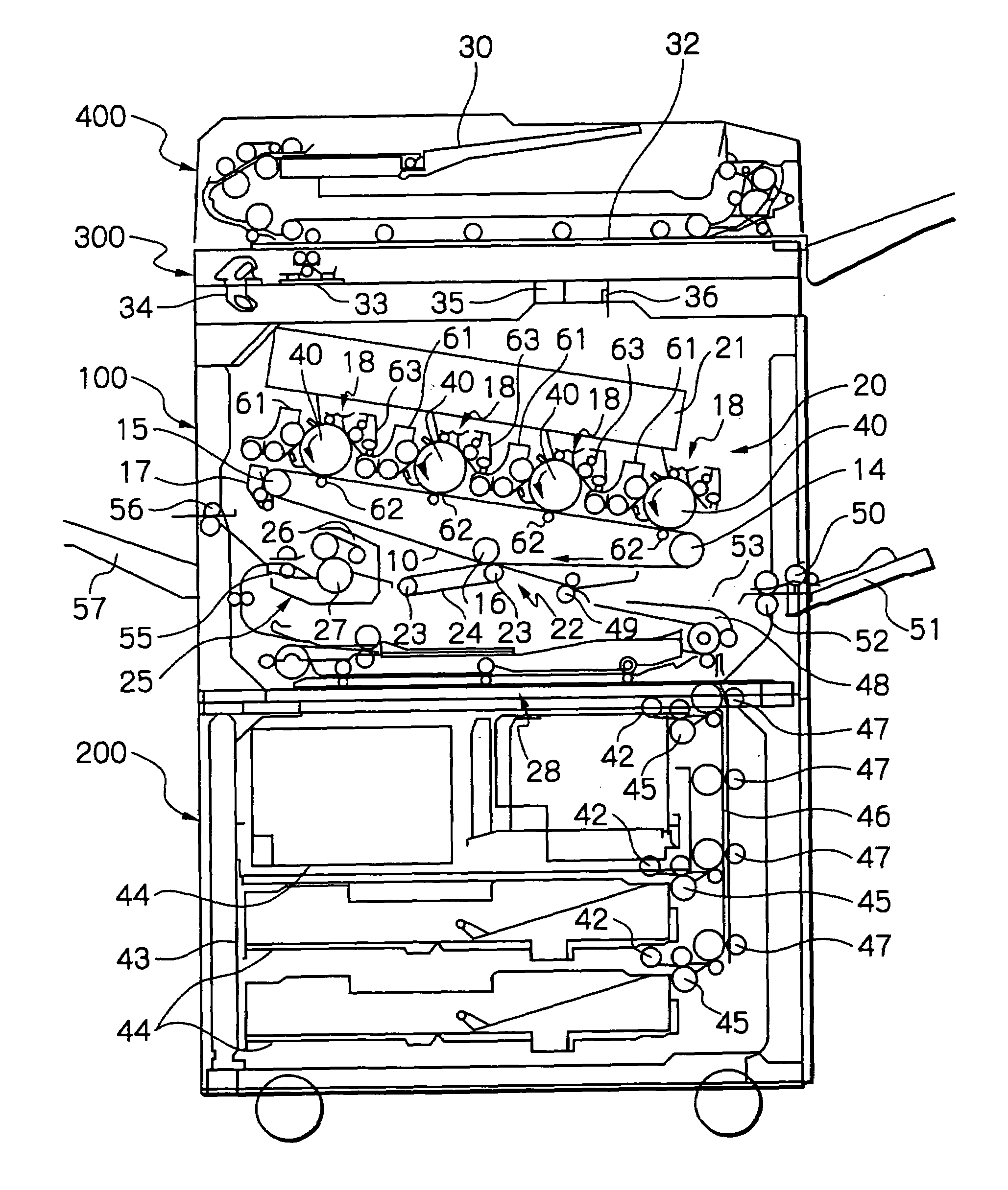
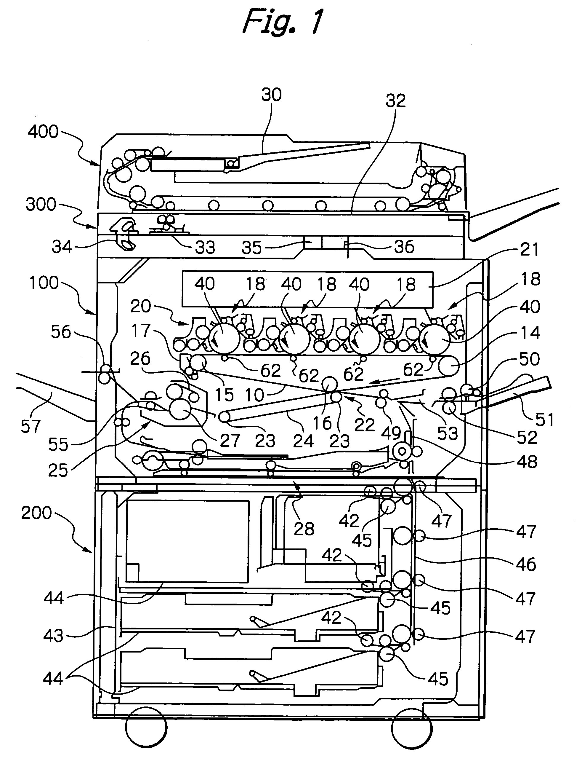
[0049]Referring to FIG. 1 of the drawings, an image forming apparatus embodying the present invention is shown and implemented as a color copier by way of example. As shown, the color copier is generally made up of a copier body 100, a sheet feed table 200 on which the copier body 100 is mounted, a scanner 300 mounted on the copier body 100, and an ADF (Automatic Document Feeder) 400 mounted on the scanner 300.

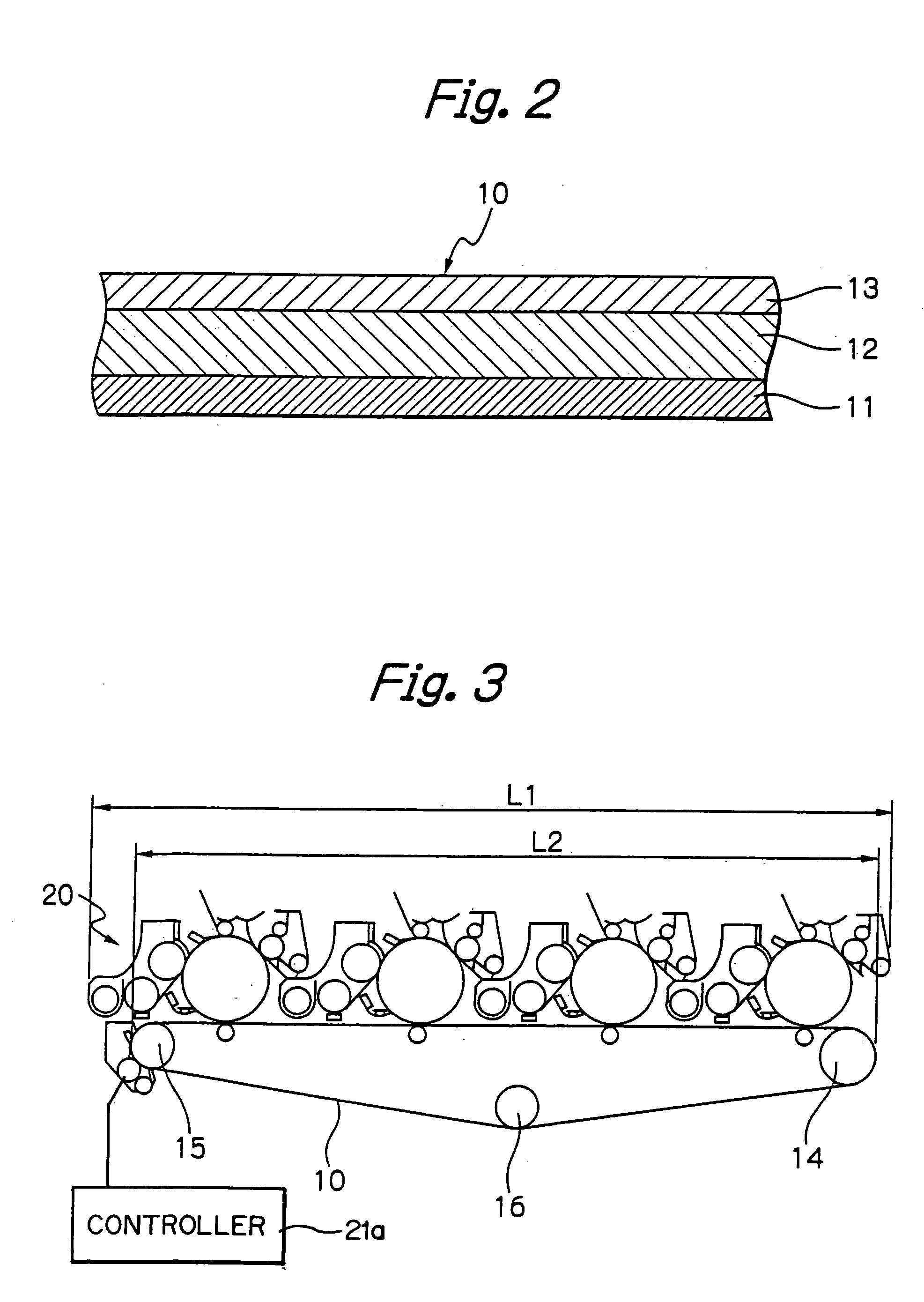
[0050]An intermediate image transfer body 10 is positioned at the center of the copier body 100 and implemented as an endless belt (transfer belt 10 hereinafter). As shown in FIG. 2 specifically, the transfer belt 10 is a laminate of a base layer 11, an elastic layer 12, and a coating layer 13. The base layer 11 is formed of fluorocarbon resin, canvas or similar material that stretches little. The elastic layer 12 is formed on the base layer 11 and formed of, e.g., fluororubber or acrylonitrile-butadien copolymer rubber. The coating layer 13 covering the elastic layer 13 is fo...


PUM


Abstract

A tandem image forming device for an image forming apparatus of the present invention includes a plurality of image forming means arranged side by side along an intermediate image transfer belt. The image forming means each include a developing device and a cleaning device arranged around an image carrier. One of nearby image forming means has its cleaning device positioned above the developing device of the other image forming means, e.g., an agitating section forming part of the image forming means. This configuration insures smooth circulation of a developer and therefore obviates an irregular developer distribution while reducing the overall size of the image forming device.

Description

BACKGROUND OF THE INVENTION [0001]1. Field of the Invention[0002]The present invention relates to a tandem image forming device including a plurality of image forming means, each of which forms a toner image on a respective image carrier, arranged side by side along an intermediate image transfer body implemented as a belt or along a path for conveying a paper sheet or similar recording medium. Also, the present invention relates to a copier, printer, facsimile apparatus or similar color image forming apparatus including a tandem image forming device.[0003]2. Description of the Background Art[0004]A tandem image forming device includes a plurality of image forming means arranged side by side and each including a charger, an exposing device, a developing device and a cleaning device arranged around an image carrier. Japanese Patent Laid-open Publication No. 9-34205, for example, discloses a color image forming apparatus in which a plurality of image forming means are simply arranged ...

Claims


Application Information

Patent Timeline
Patent Type & Authority Patents(United States)
IPC IPC(8): G03G15/16G03G15/02B65H9/14G03G15/00G03G15/01G03G15/08G03G21/00G03G21/10G03G21/14
CPCG03G15/0131G03G15/161G03G15/0194G03G2215/0119G03G2215/0132G03G2215/0141G03G2215/0129
Inventor MIYAWAKI, KATSUAKIIIJIMA, TAKESHITAKEDA, YUSUKEHIRAI, SHUJIIWAI, SADAYUKIKOSUGI, HIDEKIOBU, MAKOTO
Owner RICOH KK
Why Eureka
Try Eureka