
Aerosol injection pump

A spray pump and aerosol technology, which is applied in the field of spray pumps and aerosol spray pumps, can solve the problems of high energy consumption, large floor space, and poor versatility of atomization spray equipment, and achieve widening of application fields and application ranges, occupying The effect of small area and convenient use

Inactive Publication Date: 2014-12-17
NINGBO FUSLE MECHANICAL MFG
View PDF5 Cites 25 Cited by
  • Summary
  • Abstract
  • Description
  • Claims
  • Application Information

AI Technical Summary

Problems solved by technology

But to complete these processes, it is necessary to use the motor to drive the gear pump and the air compressor to realize the storage of compressed air. Therefore, a variety of equipment is often required, which not only consumes high energy, but also occupies a large area and requires a lot of labor.
[0004] For another example, in the electronic product manufacturing industry, the surface of some electronic products needs to be sprayed with some anti-static adhesion liquid. In order to make the liquid spray evenly, the spraying method is often used, and the liquid is often pumped out and then sprayed. Using high-pressure gas for atomization, there are also a variety of equipment combinations to achieve a single-function structure, resulting in high energy consumption and poor versatility of atomization spray equipment

Method used


Image

  • Aerosol injection pump
  • Aerosol injection pump
  • Aerosol injection pump

Examples


Embodiment Construction

[0027] The present invention will be further described below in conjunction with the accompanying drawings and embodiments. However, the uses and purposes of these exemplary embodiments are only used to illustrate the present invention, and do not constitute any form of limitation to the actual protection scope of the present invention, nor limit the protection scope of the present invention thereto.

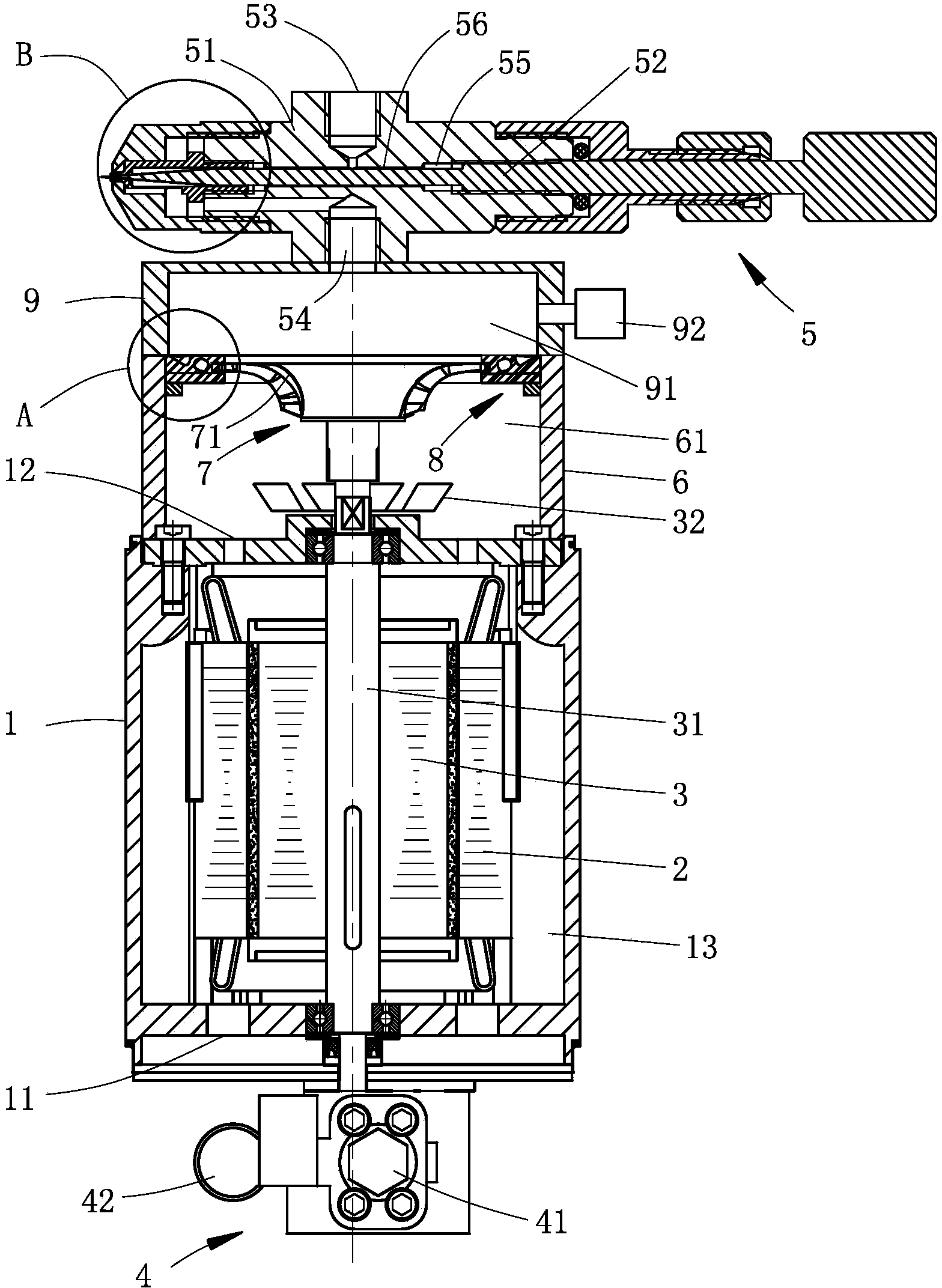
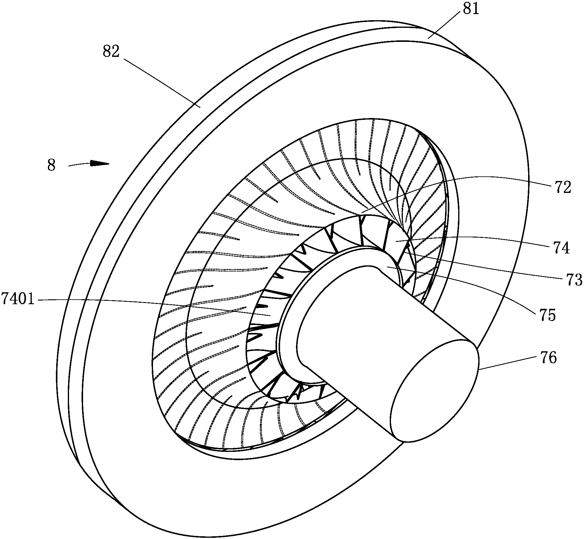
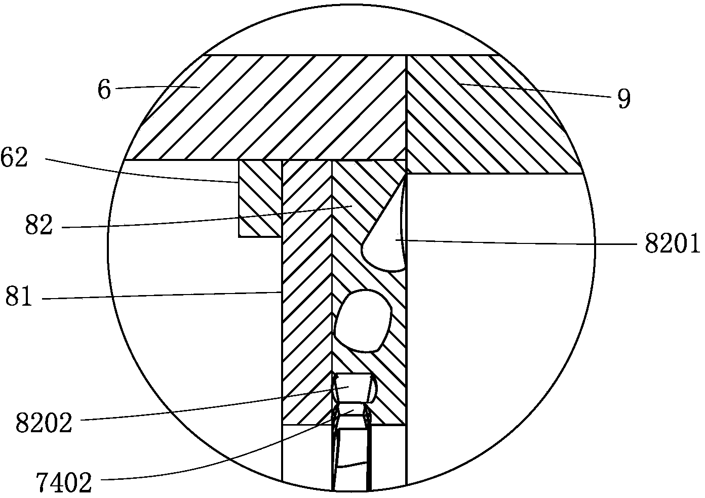
[0028] Such as figure 1 , figure 2 , image 3 and Figure 4Commonly shown, the present invention provides an aerosol jet pump, the aerosol jet pump mainly includes a casing 1, a stator winding 2 is arranged in the casing 1, a rotor winding 3 is arranged in the stator winding 2, and the rotor winding Both ends of the rotor shaft 31 of 3 protrude from the housing 1, one end of the housing 1 is provided with a gear pump 4, one end of the rotor shaft 31 is connected to the power input shaft of the gear pump 4, and the other end of the housing 1 is provided with an air pressure g...


PUM


Abstract

The invention discloses an aerosol injection pump and belongs to the technical field of liquid atomization. The aerosol injection pump comprises a casing, wherein a stator winding is arranged in the casing; a rotor winding is arranged in the stator winding; a gear pump is arranged at one end of the casing; one end of a rotor shaft is connected with a power input shaft of the gear pump; an air pressure generator is arranged at the other end of the casing and comprises an outer casing which is connected together with the casing; a fixed ring is fixedly arranged on the outer casing; an annular sliding chute is formed in an inner ring of the fixed ring; the other end of the rotor shaft is connected with a pressurizing plate; the pressurizing plate comprises an inner sleeve and an outer sleeve which are connected together; a plurality of helical blades are arranged between the inner sleeve and the outer sleeve; a gas storage cavity is formed in one side, away from the casing, of the fixed ring; the aerosol injection pump further comprises an aerosol valve; the aerosol valve is provided with an air inlet, a liquid inlet and an atomizing outlet; the gas storage cavity is communicated with the air inlet; a liquid outlet of the gear pump is communicated with the liquid inlet. The aerosol injection pump disclosed by the invention is compact in structure and good in energy-saving effect, and can be widely applied to liquid atomization.

Description

technical field [0001] The invention relates to a jet pump, more particularly to an aerosol jet pump, and belongs to the field of liquid atomization technology and corresponding devices. Background technique [0002] With the advancement of science and technology and the increasingly refined requirements of process operations, liquid atomization is used more and more widely in industrial production. It plays an important role in many industrial fields, and it is an indispensable operation step and process. [0003] For example, to spray the processed parts and do anti-rust treatment, it is necessary to use a high-pressure cleaner to extract lubricating oil, and then pump out and atomize the extracted lubricating oil through high pressure. The traditional method is to use a gear pump to pump out the lubricating oil, then use a nozzle to throttle the flow, and then spray it out with compressed air for atomization. But to complete these processes, it is necessary not only to u...

Claims


Application Information

Patent Timeline
IPC IPC(8): B05B1/06B05B7/04
CPCB05B7/0416B05B15/00
Inventor 孙伟国张时焜冯国栋董乾清严锋杰
Owner NINGBO FUSLE MECHANICAL MFG
Learn More