Roller screw and roller screw roller arranging method

Inactive Publication Date: 2001-08-30
THK CO LTD
View PDF0 Cites 27 Cited by
  • Summary
  • Abstract
  • Description
  • Claims
  • Application Information

AI Technical Summary

Benefits of technology

0023] According to the fifth aspect of the invention, as described above, since the forward-motion load roller group (17) receives the forward-motion axial direction load (1) occurring during the reciprocating motion of the roller screw and the backward-motion load roller group (18) receives the backward-motion axial direction load (2) occurring during the reciprocating motion of the roller screw, t

Problems solved by technology

However, each of the rollers, unlike the ball, is not formed symmetric (that is, it is not spherical in shape).
Therefore, in the case of the roller screw, unlike the ball screw, the direction of the axial-direction load that can be received by the roller screw is limited to one direction; and thus, the rol

Method used


Image

  • Roller screw and roller screw roller arranging method
  • Roller screw and roller screw roller arranging method
  • Roller screw and roller screw roller arranging method

Examples


first embodiment

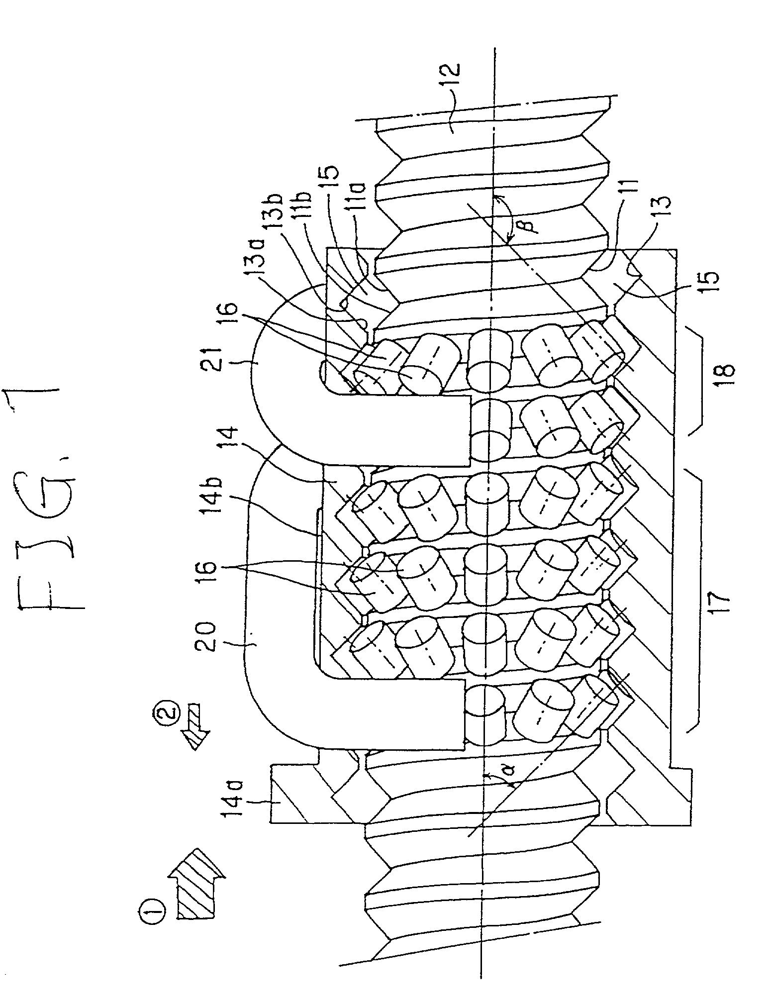
[0024] FIG. 1 is a section view showing a roller screw in the axial direction thereof according to the invention;

second embodiment

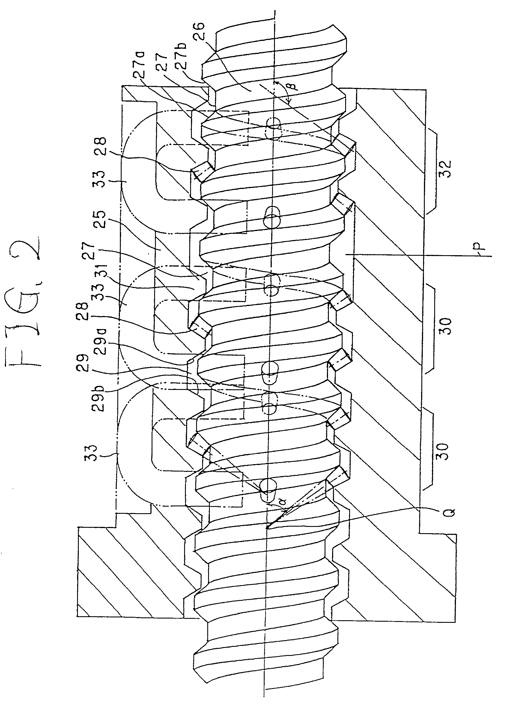
[0025] FIG. 2 is a section view showing a roller screw in the axial direction thereof according to the invention;

third embodiment

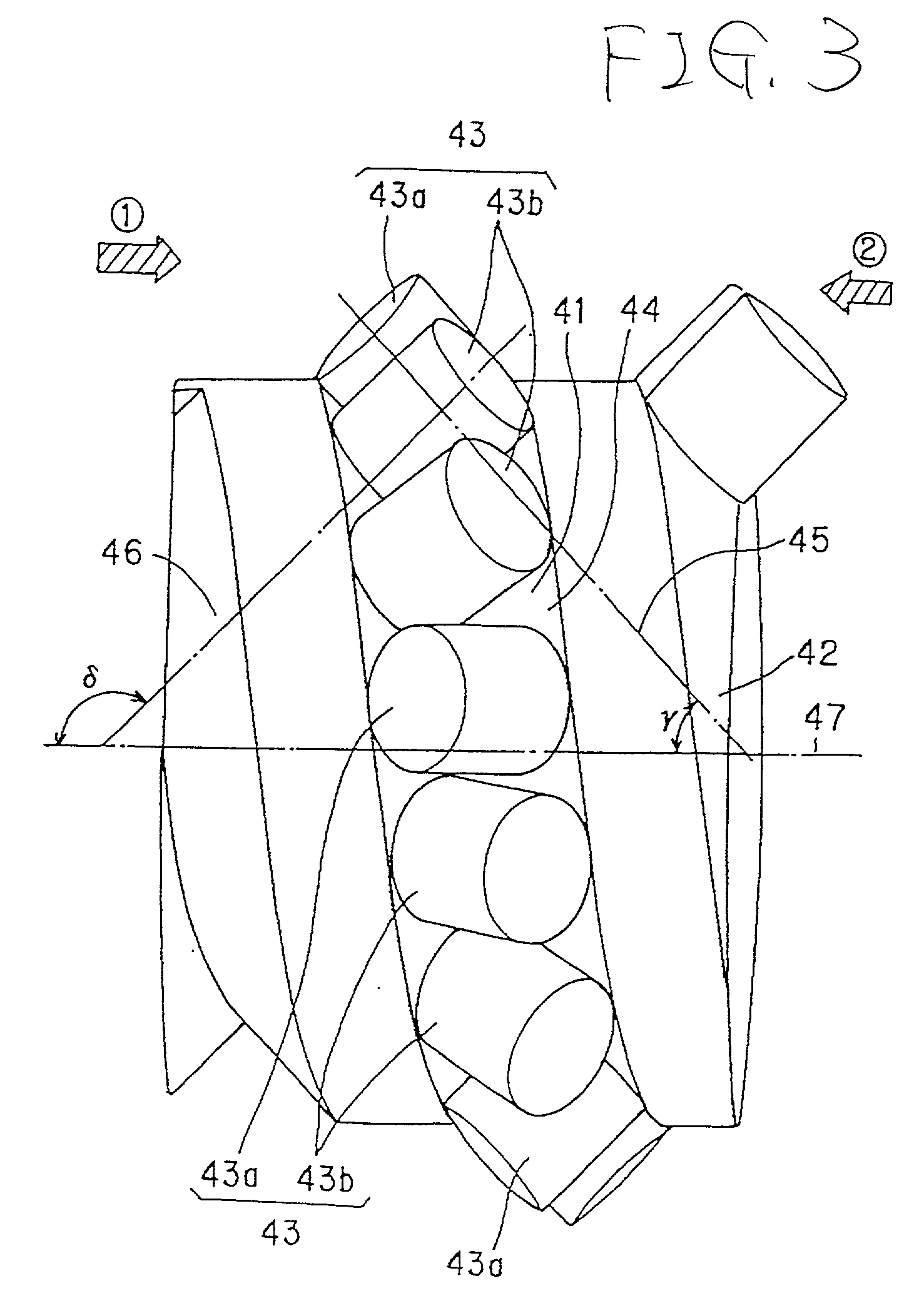
[0026] FIG. 3 is a section view showing a roller screw according to the invention, showing a screw shaft and rollers employed therein;

[0027] FIG. 4 is a view of rollers to be arranged in a load rolling passage formed in the roller screw according to the third embodiment;

[0028] FIG. 5 is a section view of a conventional ball screw in the axial direction thereof;

[0029] FIG. 6 is a section view of a conventional roller screw in the axial direction thereof; and

[0030] FIG. 7 is a view of rollers to be arranged in a roller rolling passage formed in the conventional roller screw.

[0031] Now, a description will be given in more detail of preferred embodiments of the invention with reference to the accompanying drawings.

[0032] Now, FIG. 1 shows a first embodiment of a roller screw according to the invention. This roller screw comprises a screw shaft 12 having a spiral-shaped roller rolling groove 11 formed in the outer peripheral surface thereof, a nut member 14 having a spiral-shaped load ro...


PUM


Abstract

In a roller screw, a plurality of rollers 16 interposed between a nut member 14 and a screw shaft 12 are composed of a forward-motion load roller group 17, the rollers 16 of which are arranged in such a manner that the center lines thereof are set at a given angle alpha with respect to the center line of the screw shaft 12, and a backward-motion load roller group 18, the rollers 16 of which are arranged in such a manner that the center lines thereof are set at an angle beta, which is different from the angle alpha, with respect to the center line of the screw shaft 12; and, the forward-motion load roller group 17 and backward-motion load roller group 18 are disposed such that they are separated from each other.

Description

[0001] 1. Field of the Invention[0002] The present invention relates a roller screw which comprises a screw shaft, a nut member, and a plurality of rollers interposed between the screw shaft and nut member.[0003] 2. Description of the Related Art[0004] Conventionally, there is known a ball screw in which a plurality of balls are interposed between a screw shaft and a nut member. Now, FIG. 5 shows an axial-direction section of a ball screw of this type. In case where a screw shaft 1 is rotated with respect to a nut member 2, the number member 2 is allowed to reciprocate in the axial direction of the screw shaft 1. Balls 3 are allowed to roll between the screw shaft 1 and nut member 2 along the outer periphery of the screw shaft 1. By the way, the ball screw, in some cases, can be given an axial-direction load (1) or an axial-direction load (2) as an external load. The axial-direction load (1) is an external load which occurs when the nut member 2 moves forward, whereas the axial-dire...

Claims


Application Information

Patent Timeline
IPC IPC(8): F16H25/22
CPCF16H25/2214F16H25/2247F16H2025/2271Y10T74/19758Y10T74/19744Y10T74/19753
Inventor NISHIMURA, KENTAROWKIMURA, SHINO
Owner THK CO LTD
Why Eureka
Try Eureka