System and method for installing a liner in a borehole

a technology of liner and conduit, which is applied in the directions of wellbore/well accessories, fluid removal, sealing/packing, etc., can solve the problems of difficulty in flushing the liner, no fully satisfactory results, and the difficulty of the desired flushing of the liner, so as to reduce or eliminate the obstruction of the interior of the running tool

Inactive Publication Date: 2007-04-17
SMITH INT INC
View PDF14 Cites 6 Cited by
  • Summary
  • Abstract
  • Description
  • Claims
  • Application Information

AI Technical Summary

Benefits of technology

[0046]The packer assembly and the running tool may be further comprised of a suitable structure, apparatus or device for transferring torque between the running tool and the packer assembly. The ability to transfer torque between the running tool and the packer assembly facilitates rotational manipulation of the packer assembly during the insertion and positioning of the system in the borehole.
[0062]The running tool is preferably further comprised of a running tool bypass device for bypassing a fluid from an exterior of the running tool to the interior of the running tool. The running tool bypass device may be fixed in an open position or may be actuatable from an open position to a closed position by the application of a running tool bypass actuating pressure to the interior of the running tool. The ability to actuate the running tool bypass device from the open position to the closed position provides an opportunity for the system to be used to circulate a circulating fluid through the liner conduit after it has been installed in the borehole without first removing the running tool from the borehole.
[0068]The circulating conduit facilitates the passing of the circulating fluid through the liner conduit after the liner conduit has been installed in the borehole but before the running tool has been removed from the borehole. The circulating conduit is particularly beneficial where the liner conduit is a perforated liner conduit since the perforations will interfere with the passing of circulating fluid directly through the liner conduit. The inclusion of the circulating conduit as part of the system also provides an opportunity for the liner conduit to be installed in the borehole and for the circulating fluid to be passed through the liner conduit in a single operation without the need first to remove the running tool from the borehole and then to insert a separate circulating conduit into the borehole.
[0071]The system facilitates the application of the various actuating pressures for performing the various functions of the packer assembly and the running tool. Preferably, the interior of the running tool defines a flowpath therethrough, which flowpath may be obstructed in order to create a backpressure to facilitate the application of the various actuating pressures. Where the system is comprised of the circulating conduit, preferably the obstruction of the flowpath through the interior of the running tool either does not prevent the passing of the circulating fluid through the running tool and the circulating conduit, or the obstruction may be lessened or eliminated to enable the passing of the circulating fluid. The flowpath may be obstructed in any suitable manner which achieves these goals.
[0073]Preferably the setting plug landing surface is associated with the running tool bypass device. More preferably the setting plug landing surface is associated with the running tool bypass valve so that the actuation of the running tool bypass device to the closed position also results in a lessening or elimination of the obstruction of the interior of the running tool.

Problems solved by technology

However, none have been found to be fully satisfactory.
However, the running tool with the packer may not be easily or readily insertable in the borehole due to the occurrence of a “piston” effect in the borehole during installation.
In this case, the presence of the fluid bypass may render any such desired flushing of the liner more difficult.
Thus, the absence of a fluid bypass may render the running tool and packer more difficult to conduct through the lateral borehole to the desired downhole position.
However, the presence of the fluid bypass may render the subsequent flushing of the liner more difficult.
Further, the manner of actuating the packer and the releasing the running tool therefrom have not been found to be fully satisfactory.
However, such mechanically actuated or mechanically manipulated systems may cause various difficulties.
For example, if the working string or any of the attached apparatus or liner becomes stuck within the borehole, it may not be possible to manipulate the working string in the desired manner to set the packer and / or release the running tool.
Thus, manipulation of the working string, and particularly rotation of the working string, to set the packer may cause the packer to accidentally unthread from the running tool.
Accordingly, such mechanically actuated systems may not always be desirable.
As well, the difficulties experienced with these mechanical systems may be intensified depending upon the orientation and depth of the borehole.
In particular, the use of mechanical systems in long reach horizontal lateral boreholes has been found to be particularly challenging.

Method used


Image

  • System and method for installing a liner in a borehole
  • System and method for installing a liner in a borehole
  • System and method for installing a liner in a borehole

Examples


Embodiment Construction

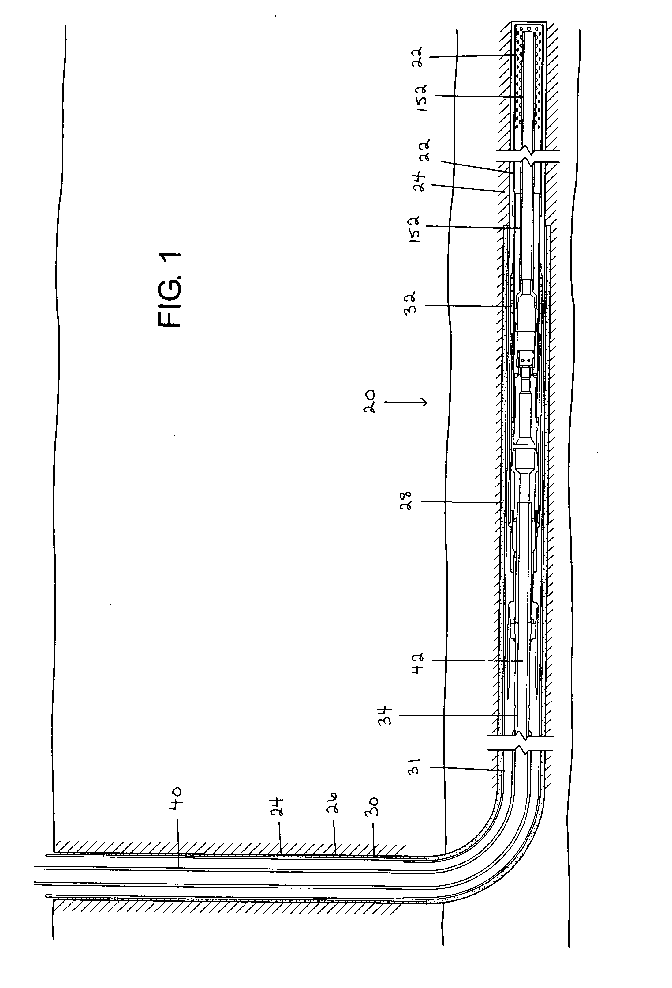
[0107]Referring to FIGS. 1 and 8–14, the within invention is directed at a system (20) and a method for installing a liner conduit (22) in a borehole (24). The liner conduit (22) may be installed or positioned at any location along the length of the borehole (24). However, preferably, the borehole (24) is comprised of a primary borehole section (26) extending from the surface to a desired depth and at least one lateral borehole section (28) extending from the primary borehole section (26). The lateral borehole section (28) may extend from the primary borehole section (26) at any angle and may be oriented in any direction relative to the surface. However, preferably, the lateral borehole section (28) is not oriented vertically or perpendicular to the ground surface. Rather, the lateral borehole section (28) is preferably deviated from the vertical. In the preferred embodiment, the lateral borehole section (28) is oriented in a generally or substantially horizontal direction.

[0108]Thu...


PUM


Abstract

A system and a method for installing a liner conduit in a borehole. The system includes a packer assembly, a running tool or a packer assembly and a running tool. The method uses a packer assembly and a running tool for installing a liner conduit in a borehole. The system and the method both use pressure to perform functions relating to the system and the method.

Description

CROSS-REFERENCE TO RELATED APPLICATIONS[0001]The present application claims priority to Canadian Application No. 2,462,012 filed on Mar. 23, 2004 and entitled “System and Method for Installing a Liner in a Borehole,” hereby incorporated herein by reference for all purposes.FIELD OF INVENTION[0002]The present invention relates to a system and a method for installing a liner conduit in a borehole, preferably a long reach horizontal borehole. Further, the system is preferably comprised of at least one of a packer assembly adapted for insertion in the borehole with a running tool and a running tool adapted for insertion in the borehole with a packer assembly, both of which are actuated hydraulically. The method is preferably performed utilizing the within system.BACKGROUND OF INVENTION[0003]Directional drilling technology permits the drilling of a lateral or secondary borehole from a primary or mother borehole. Typically, lateral boreholes are drilled, and subsequently produced, through...

Claims


Application Information

Patent Timeline
Patent Type & Authority Patents(United States)
IPC IPC(8): E21B23/06E21B33/12E21B23/00E21B33/128E21B33/129E21B33/1295
CPCE21B23/06E21B33/128E21B33/1294
Inventor RICALTON, ALLEN E.MAJKOVIC, DAVOR
Owner SMITH INT INC
Why Eureka
Try Eureka