Pedal stroke adjuster for bicycles or the like

a technology of pedal stroke and adjuster, which is applied in the field of pedal stroke adjuster for bicycles and stroke adjusters, can solve the problems of inability to adjust, uncomfortable operation of the same bicycle by persons with unusually long legs, and significant problems for many bicyclists, and achieve the effect of simplifying the manufacture and distribution of such devices

Inactive Publication Date: 2007-04-17
ANDREWS RONALD A
View PDF15 Cites 42 Cited by
  • Summary
  • Abstract
  • Description
  • Claims
  • Application Information

AI Technical Summary

Benefits of technology

[0011]The invention provides a pedal stroke adjuster which enables changing of the diameter of the orbit that is traveled by one or both foot pedals of a particular bicycle in order to accommodate to the needs of different persons. The, adjuster has a configuration which is compatible with any of a variety of different bicycle crank arms having different sizes and shapes. It is not necessary to vary the design of the attachment in order to accommodate to differing crank arms. This provides for more widespread use of pedal stroke adjusters by simplifying the manufacture and distribution of such devices.

Problems solved by technology

Thus, in an unmodified conventional bicycle, both pedals must be traveled around orbits that are of equal diameter and which are of fixed size.
This can cause significant problems for many bicyclists.
Smaller persons may have difficulty operating a bicycle having a pedal orbit that is proportioned for an adult of average size or, in extreme cases, may find that to be impossible.
Operation of the same bicycle by persons who have unusually long legs may be uncomfortable.
Use of stroke adjusters of this kind as heretofore configured has been undesirably complicated as bicycle crank arms do not have a single standardized shape.
Consequently, components of prior stroke adjusters which fasten the attachment to a crank arm are designed for use with a crank arm of a specific shape and in many cases are not easily attachable to crank arms having other configurations.

Method used


Image

  • Pedal stroke adjuster for bicycles or the like
  • Pedal stroke adjuster for bicycles or the like
  • Pedal stroke adjuster for bicycles or the like

Examples


Embodiment Construction

[0020]For purposes of example the invention will herein be described as applied to a bicycle. It should be recognized that the invention is also applicable to other devices which are operated by manual revolving of foot pedals such as certain stationary exercising machines for example.

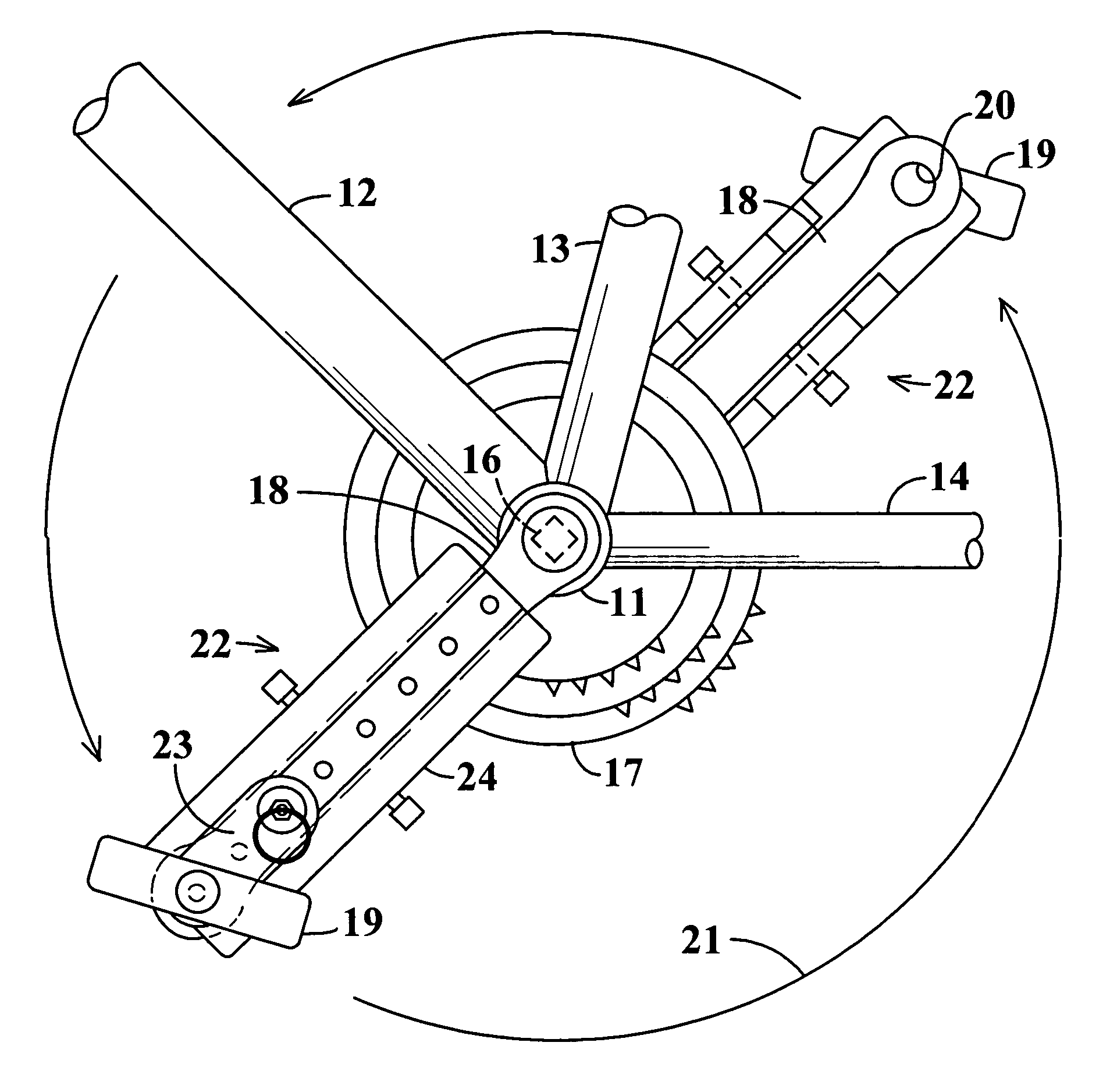
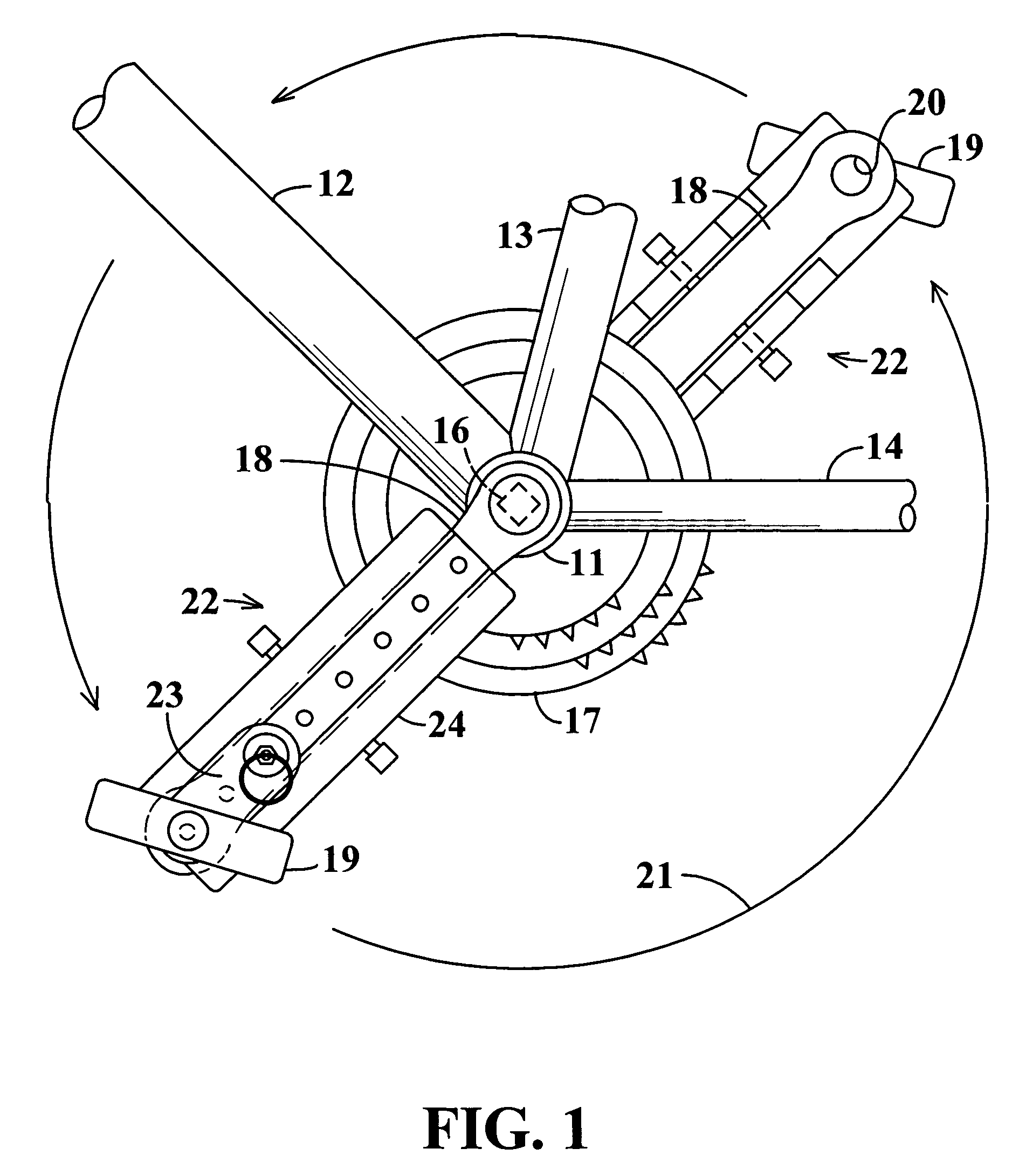
[0021]Referring initially to FIG. 1 of the drawings, components of a bicycle include a hub 11 from which frame members 12, 13 and 14 extend to connect to other components that are not depicted in the drawing as the bicycle itself may be of conventional construction. The hub 11 functions as a bearing for the axle 16 of a sprocket gear assembly 17 which turns a wheel of the bicycle by means of a drive chain which components are also not shown as they may be of any of the known constructions. Axle 16 and sprocket gear assembly 17 are turned by two crank arms 18 which extend in opposite radial directions relative to the axis of rotation of the axle and which are at opposite sides of the bicycle. Swiveling ...


PUM


Abstract

A stroke adjusting attachment for bicycles or the like enables selective changing of the diameter of the orbit which is traveled by a foot pedal to adapt a particular bicycle to persons having different leg lengths or who may have physical impairments which limit foot movement. The pedal is fastened to the attachment rather than being directly secured to a crank arm of the bicycle in the conventional manner. A track member is secured to the bicycle crank arm and the pedal is fastened to a slider which is travelable to any of a plurality of different locations along the track member. Blades extend from the track member adjacent to opposite surfaces of the crank arm thereby maintaining the attachment in a fixed orientation relative to the crank arm. A particular attachment of this form can be fitted onto a variety of crank arms of different sizes and shapes.

Description

CROSS-REFERENCE TO RELATED APPLICATION[0001]This application claims subject matter disclosed in U.S. Provisional Application No. 60 / 490,095 entitled “Bicycle Pedal Stroke Adjusting Mechanism” and which was filed on Jul. 25, 2003 by Roland A. Andrews.STATEMENT REGARDING FEDERALLY SPONSORED RESEARCH OR DEVELOPMENT[0002](Not Applicable)BACKGROUND OF THE INVENTION[0003]This invention relates to bicycles or similar devices which are operated by manual turning of foot pedals in circular orbits. More particularly the invention relates to stroke adjuster attachments for selectively changing the diameter of the orbits which are traveled by the pedals in devices of this type.[0004]The foot pedals of a bicycle or the like are mounted on two crank arms that extend in opposite radial directions from the rotary axis of a drive sprocket. In a conventional bicycle the crank arms are of equal length and the pedals are situated at the ends of the crank arms. Thus, in an unmodified conventional bicycl...

Claims


Application Information

Patent Timeline
Patent Type & Authority Patents(United States)
IPC IPC(8): A63B22/06G05G1/00A63B22/08
CPCB62M3/02A63B22/0046A63B2022/0623Y10T74/2075A63B22/0605
Inventor ANDREWS, RONALD A.
Owner ANDREWS RONALD A
Why Eureka
Try Eureka