Longitudinally flexible expandable stent

a flexible, long-term technology, applied in the field of endoprosthesis devices, can solve problems such as large gaps, improper vessel support, and vessel trauma

Inactive Publication Date: 2007-04-17
BOSTON SCI SCIMED INC
View PDF164 Cites 77 Cited by
  • Summary
  • Abstract
  • Description
  • Claims
  • Application Information

AI Technical Summary

Benefits of technology

[0012]It is a goal of the present invention to provide a flexible stent formed of interconnected bands which provides for side branch access and which further avoids the problem of pinching or overlap between adjacent bands. Pinching or overlap is avoided where peaks and troughs of adjacent bands are circumferentially displaced relative to each other. The stents of the present invention accomplish this goal by having different bands characterized by different wavelengths over the length of the stent and / or disposing the interconnecting members in such a way that after expansion of the stent, the phase relationship between adjacent bands is altered with the peaks and troughs displaced circumferentially relative to each other.

Problems solved by technology

Unfortunately, a problem with such stents is that binding, overlapping or interference can occur between adjacent segments on the inside of a bend due to the segments moving toward each other and into contact or on the outside of a bend the segments can move away from each other, leaving large gaps.
This can lead to improper vessel support, vessel trauma, flow disturbance, kinking, balloon burst during expansion, and difficult recross for devices to be installed through already implanted devices and to unsupported regions of vessel.
A diamond configuration with diagonal connections between each and every diamond of each segment is also known but such closed configurations lack flexibility.

Method used


Image

  • Longitudinally flexible expandable stent
  • Longitudinally flexible expandable stent
  • Longitudinally flexible expandable stent

Examples


Embodiment Construction

[0039]While this invention may be embodied in many different forms, there are described in detail herein specific preferred embodiments of the invention. This description is an exemplification of the principles of the invention and is not intended to limit the invention to the particular embodiments illustrated.

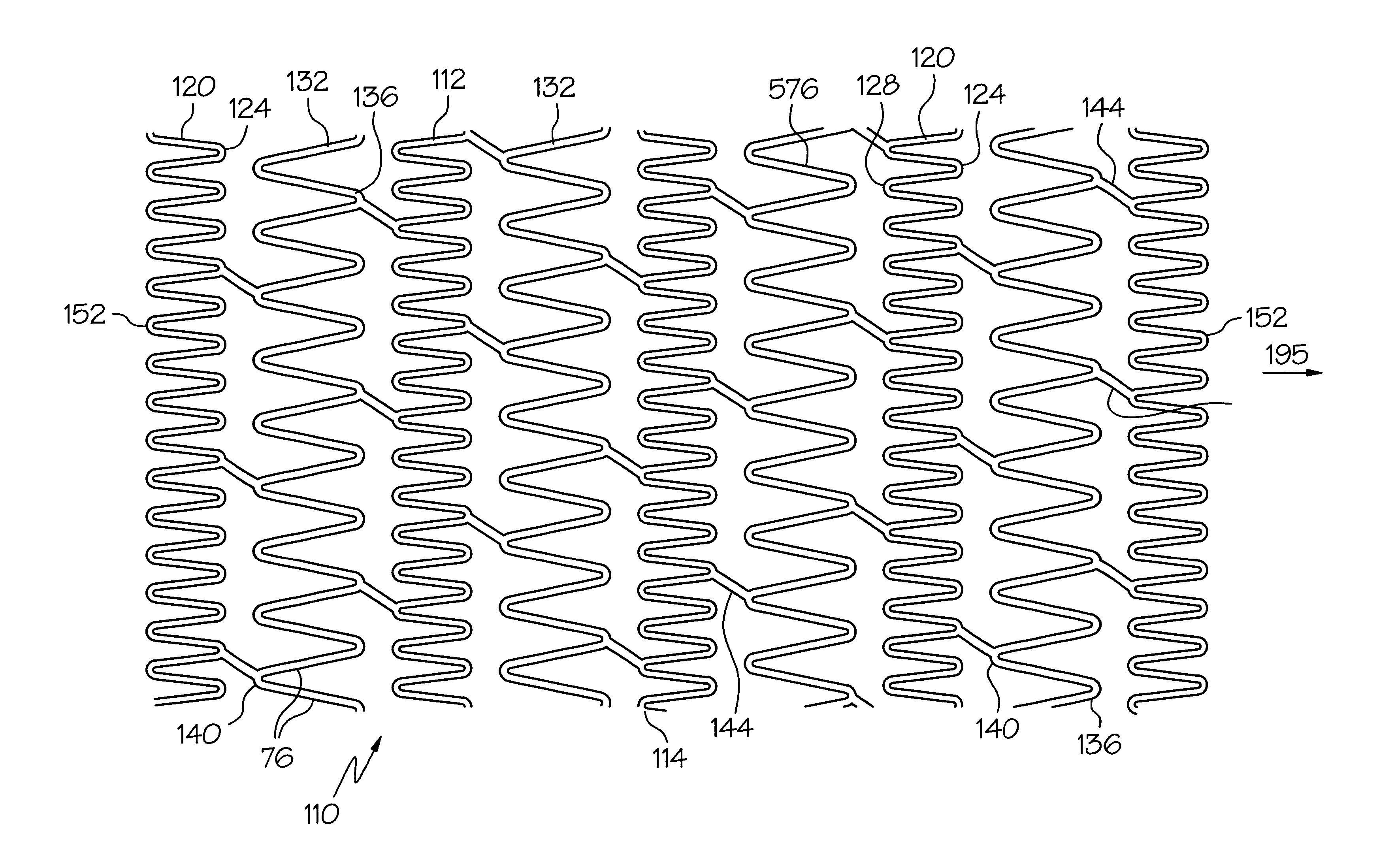
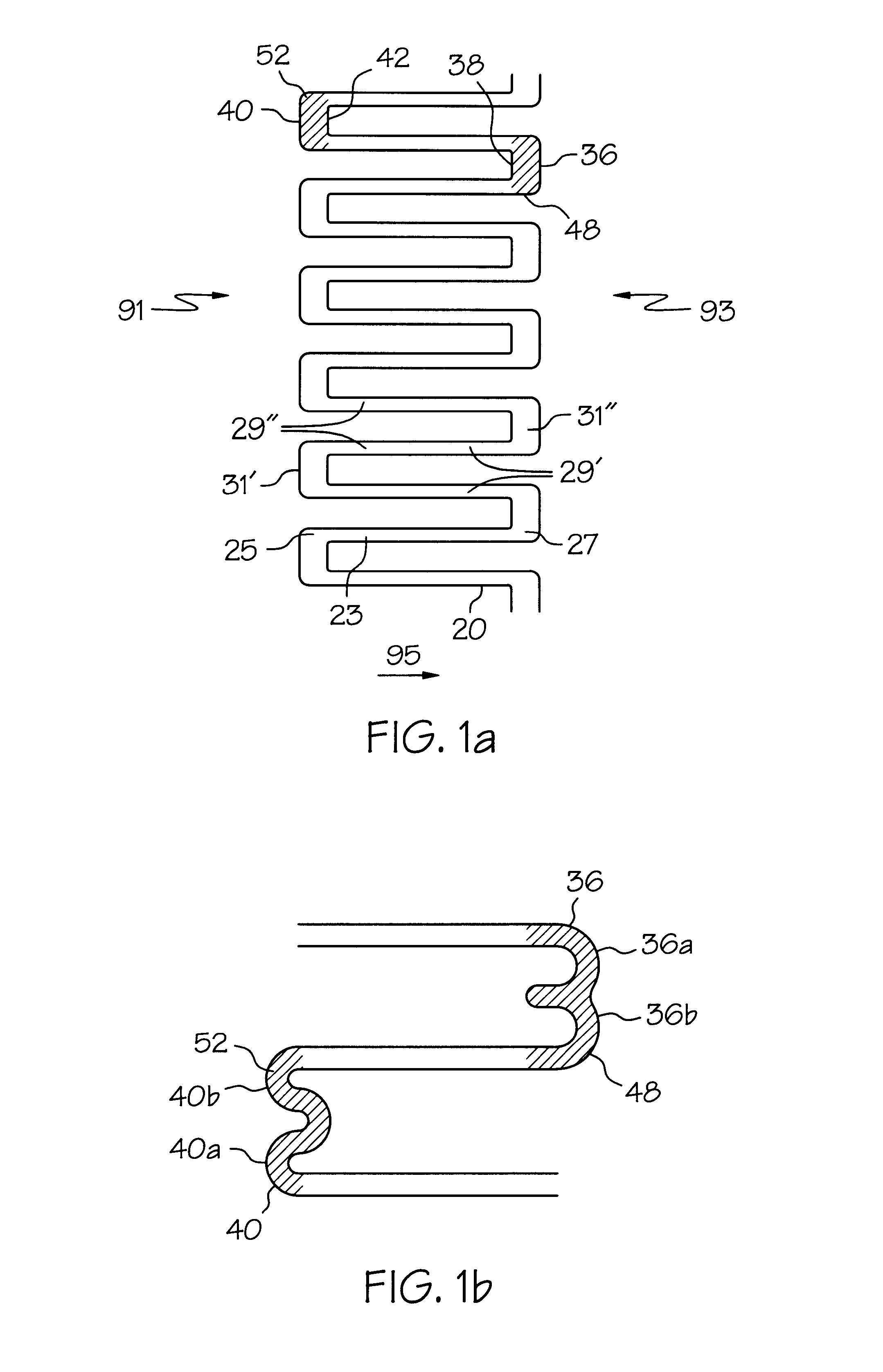
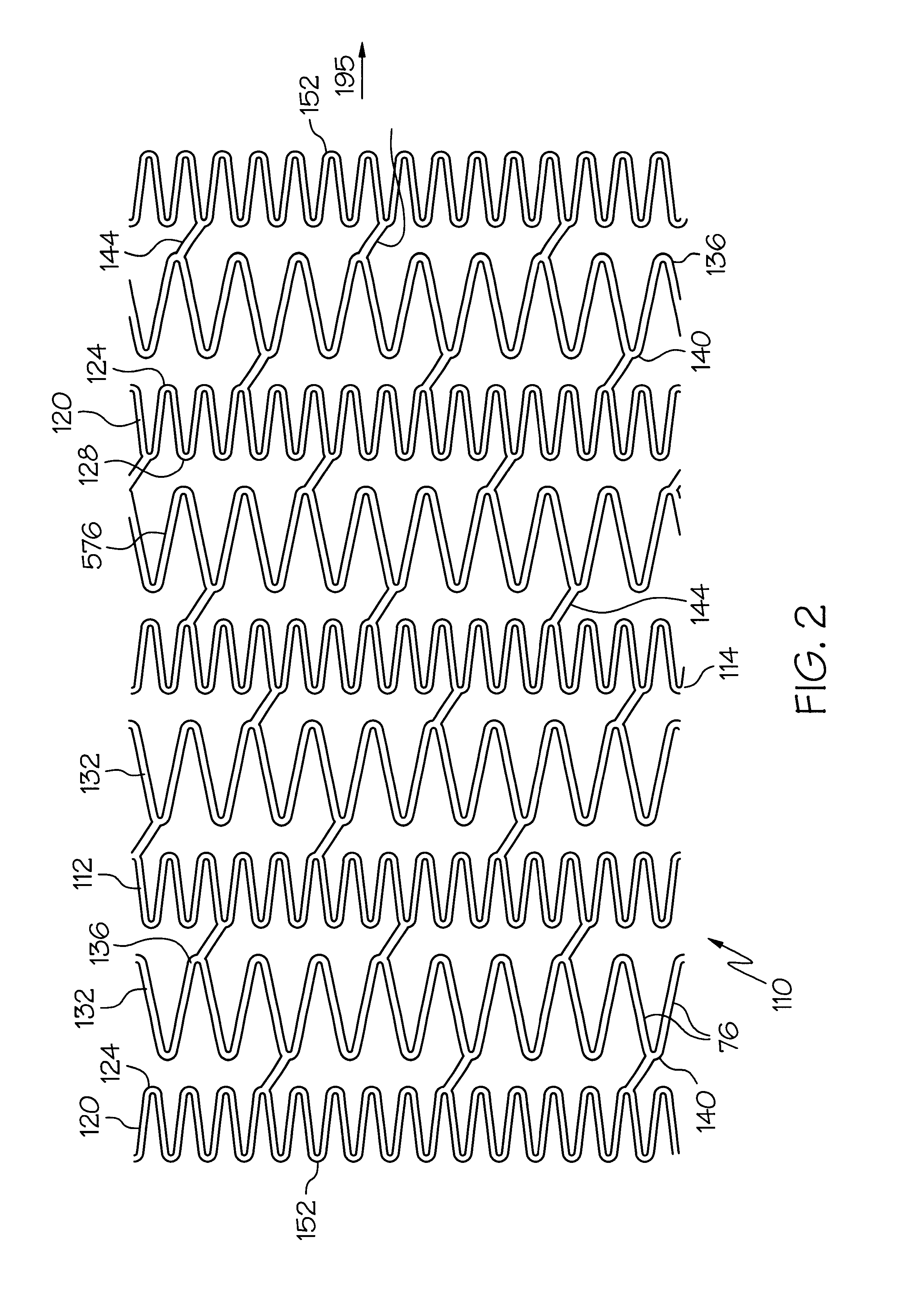
[0040]For the sake of consistency, the terms ‘peak’ and ‘trough’ shall be defined with respect to the proximal and distal ends of the stent. Each of the stents has a proximal end 91 and a distal end 93 and a longitudinal axis 95, as seen in FIG. 1a. Peaks 36 are generally concave relative to the proximal end of the stent and generally convex relative to the distal end of the stent. Troughs 40, on the other hand, are generally convex relative to the proximal end of the stent and generally concave relative to the distal end of the stent. Notwithstanding this definition, the term peak is also intended to extend to regions 48 that are generally peak-like which may, nevertheless, ...


PUM


Abstract

Segmented articulatable stent of open structure comprised of end-connected struts of first and second lengths making up first and second segments with angular interconnects between adjacent first and second segments.

Description

[0001]This application is a Continuation-in-Part of application Ser. No. 08 / 511 1076 filed Aug. 3, 1995, the disclosure of which is hereby incorporated by reference, which is a Continuation-in-Part of application Ser. No 08 / 396,569, filed Mar. 1, 1995 (abandoned).FIELD OF THE INVENTION[0002]This invention relates to an endoprosthesis device for implantation within a body vessel, typically a blood vessel. More specifically, it relates to a tubular expandable stent of improved longitudinal flexibility.BACKGROUND OF THE INVENTION[0003]Stents are placed or implanted within a blood vessel for treating stenoses, strictures or aneurysms therein. They are implanted to reinforce collapsing, partially occluded, weakened, or dilated sections of a blood vessel. They have also been implanted in the urinary tract and in bile ducts.[0004]Typically, a stent will have an unexpanded (closed) diameter for placement and an expanded (opened) diameter after placement in the vessel or the duct. Some stent...

Claims


Application Information

Patent Timeline
Patent Type & Authority Patents(United States)
IPC IPC(8): A61F2/06A61F2/00A61F2/90
CPCA61F2/91A61F2/89A61F2/88A61F2/82A61F2/915A61F2230/0054A61F2002/91508A61F2002/91516A61F2002/91525A61F2002/91533A61F2002/91558A61F2002/91583A61F2210/0019A61F2250/0018A61F2220/005A61F2220/0058
Inventor BROWN, BRIAN J.DAVIS, MICHAELFRIESEN, DAVIDLEY, TIMOTHY J.SKUBITZ, SEAN P.
Owner BOSTON SCI SCIMED INC
Why Eureka
Try Eureka