Electromagnetic relay

Active Publication Date: 2007-04-17
ORMON CORP
View PDF6 Cites 43 Cited by
  • Summary
  • Abstract
  • Description
  • Claims
  • Application Information

AI Technical Summary

Benefits of technology

[0011]Preferably, the card has a reduced thickness portion that is guided by the card acceptance portions. For, when ribs for reinforcing the reduced thickness po

Problems solved by technology

Therefore, the protuberances of the card come into sliding contact with the moving contact plate and generate wear dust, or the like.
The wear dust adhering to contacts is likely to deterior

Method used


Image

  • Electromagnetic relay
  • Electromagnetic relay
  • Electromagnetic relay

Examples


Embodiment Construction

[0031]Embodiments of the invention will be hereinafter explained with reference to the accompanying drawings.

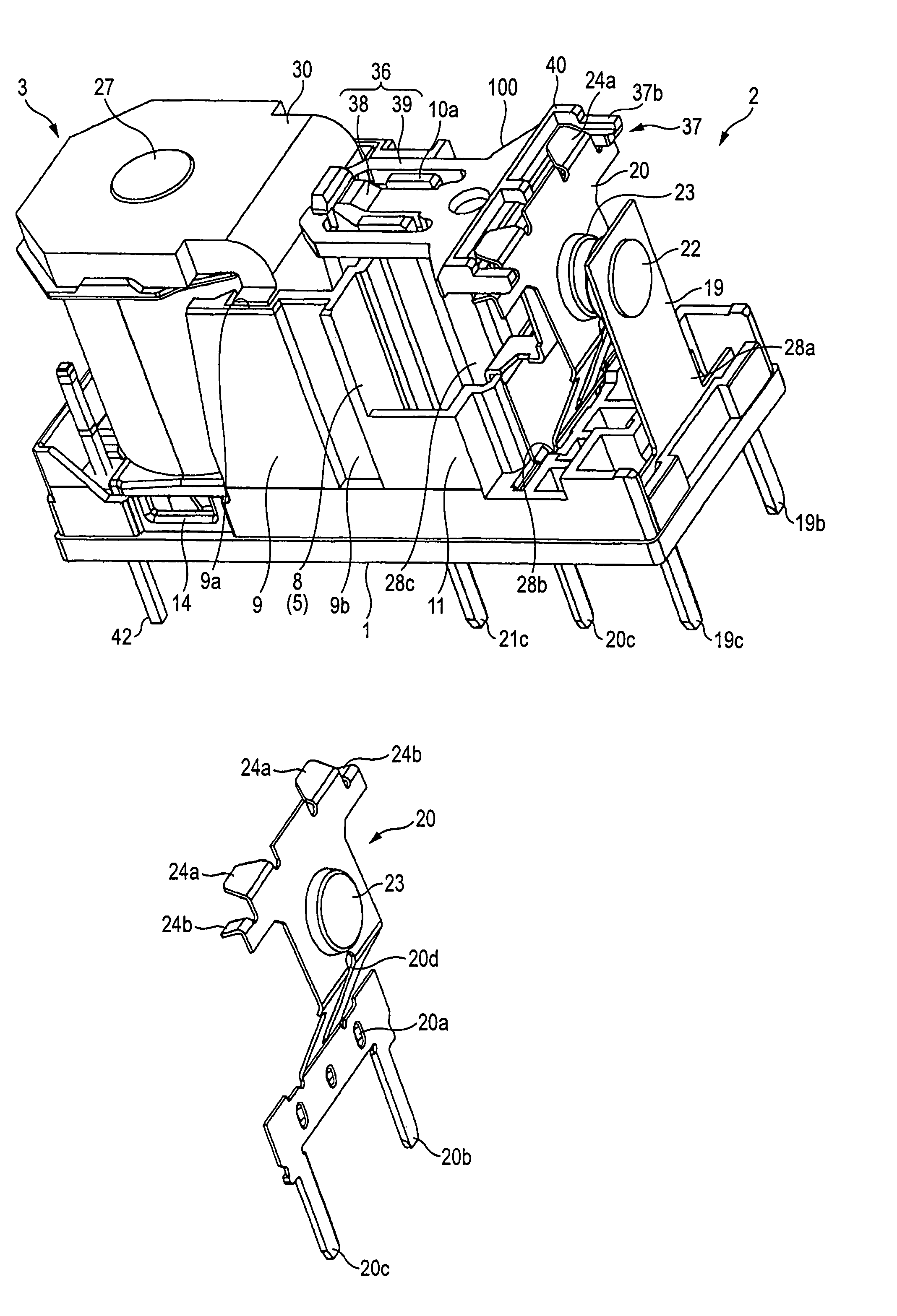
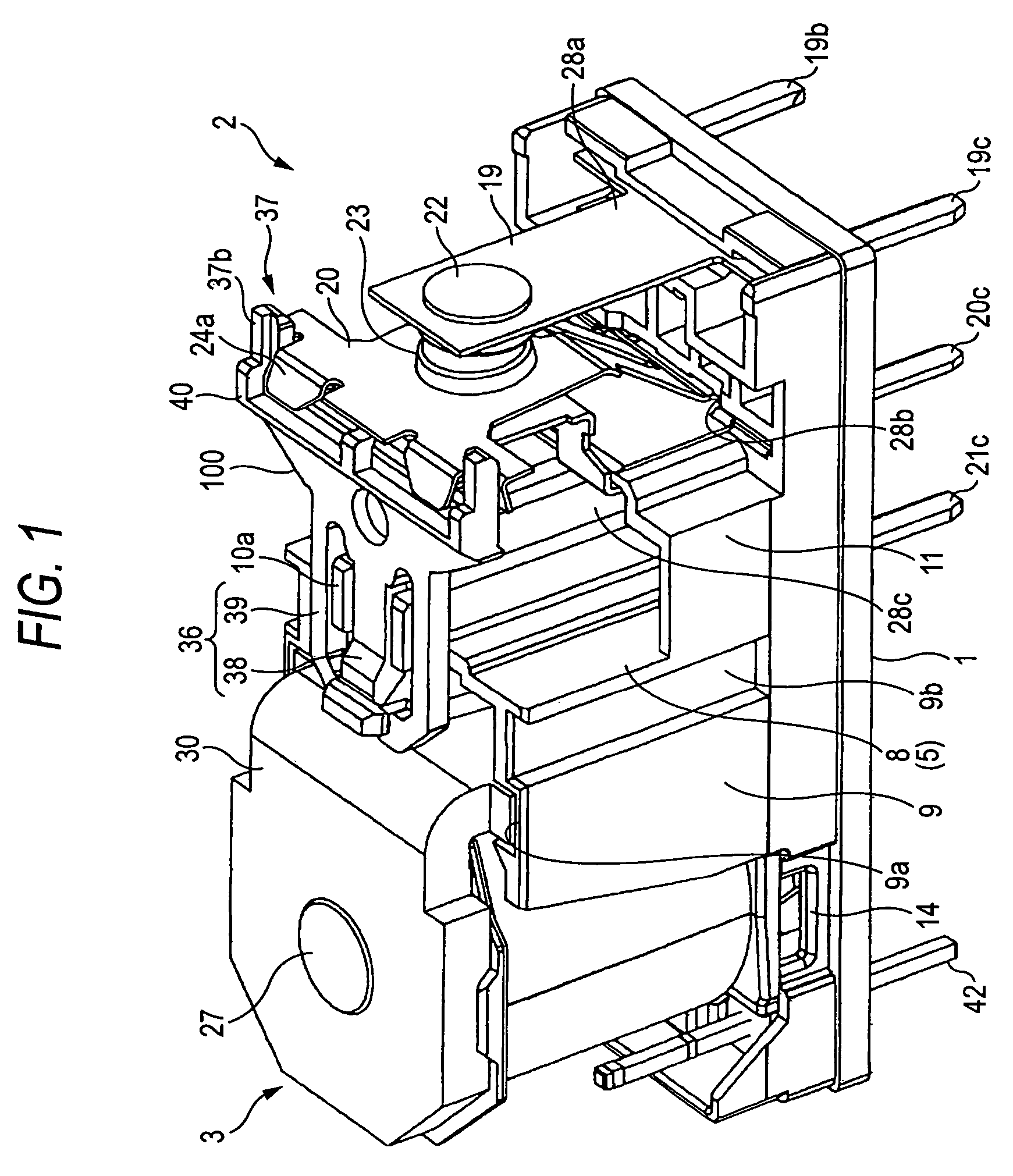
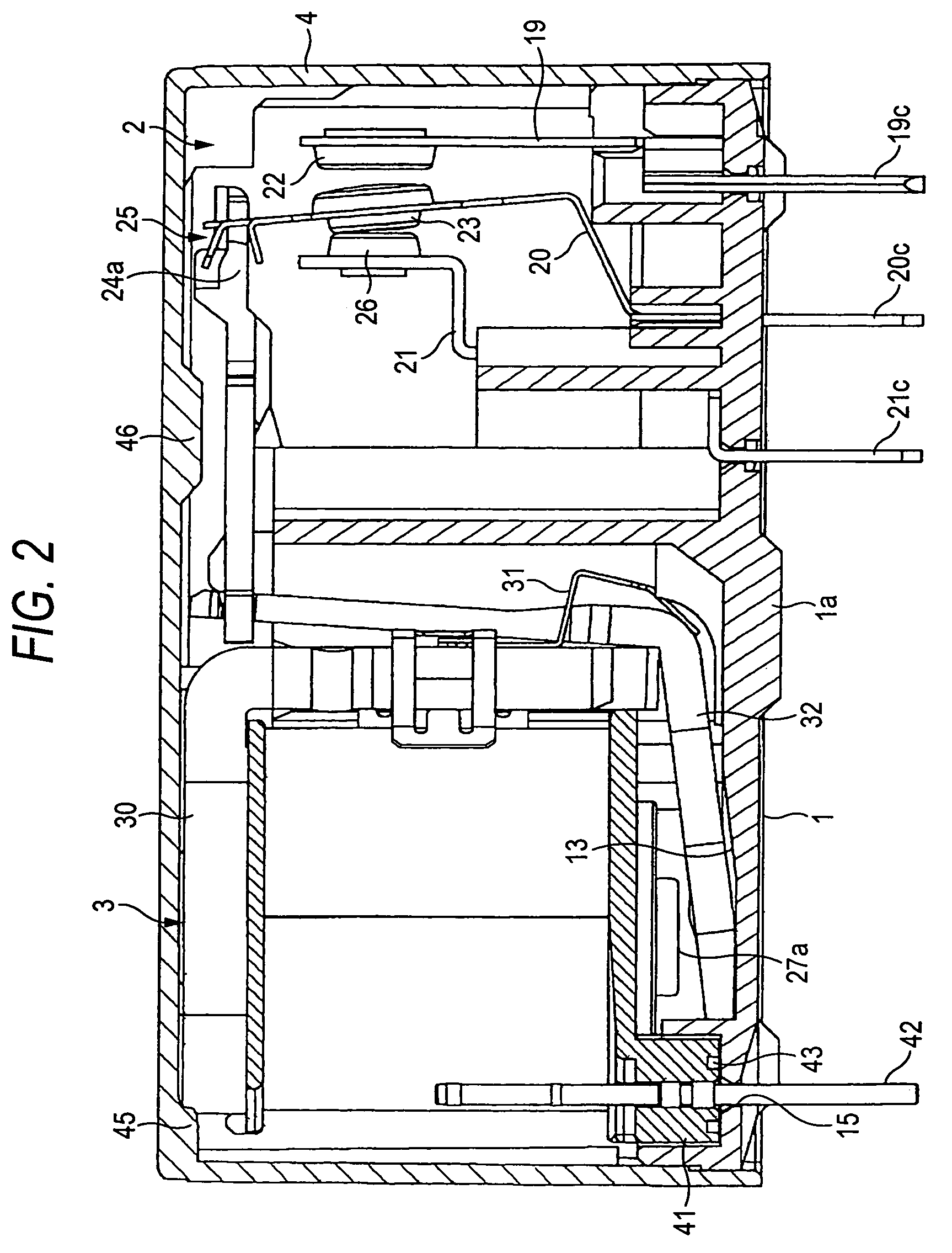
[0032]FIGS. 1 and 2 show an electromagnetic relay according to an embodiment. The electromagnetic relay briefly has a construction in which a contact switch mechanism 2 and a coil block 3 are arranged on a base 1 and these constituents are covered with a case 4.

[0033]An insulating wall 5 divides the base 1 into a coil block-fitting portion 6 and a contact switch mechanism-fitting portion 7 as shown in FIGS. 8 to 10.

[0034]The insulating wall 5 has a partition portion 8 and both side portions 9. Protuberance portions 10 are so formed at the center of the partition portion 8 as to extend in a vertical direction with a predetermined gap between them. The protuberance portions 10 reinforce the partition portion 8 and guide with their upper edge protuberance portions 10a a card 100 that will be later described. An auxiliary insulating wall 11 is formed at a lower part of each protu...


PUM


Abstract

An electromagnetic relay having a moving contact plate and fixed contact plates juxtaposed with one another on a base. A moving iron plate is rotated during magnetization/demagnetization of a coil block put on the base to reciprocate a card in a horizontal direction. The moving contact plate is allowed to undergo elastic deformation so that a contact on the moving contact plate is brought into contact and out of contact with contacts on the fixed contact plates. The top corners of the moving contact plate is bent into an upper component and a lower components in such a fashion as to form card acceptance portions, and a distal end portion of the card is brought into contact with an inner surface of the card acceptance portions.

Description

BACKGROUND OF THE INVENTION[0001]1. Field of the Invention[0002]This invention relates to an electromagnetic relay.[0003]2. Description of the Related Art[0004]A known electromagnetic relay employs a construction in which a moving contact plate is allowed to undergo elastic deformation through a card to thereby open and close contacts (refer to patent reference 1, for example).[0005]Patent reference 1:Microfilm of Japanese Utility Model Application No.23090 / 1991 (JP-UM-A-4-119947)[0006]In the electromagnetic relay of the prior art described above, however, first and second protuberances are formed on the card, the first protuberance is inserted through a through-hole formed in the moving contact plate to guide the card and the second protuberance can be pushed and brought into contact with the moving contact plate. The card is formed of a resin and the moving contact plate is formed of a metal. Therefore, the protuberances of the card come into sliding contact with the moving contac...

Claims


Application Information

Patent Timeline
IPC IPC(8): H01H51/22H01H50/26H01H50/56H01H50/64
CPCH01H50/642
Inventor SANADA, HIRONORITANAKA, HIROYASUYAMAZAKI, HIROAKI
Owner ORMON CORP
Why Eureka
Try Eureka