Compact electronic viewfinder

a technology of electronic viewfinder and compact structure, which is applied in the field can solve the problems of complicated design of compact electronic viewfinder and severe constraints in the design of evf viewing optics, and achieve the effect of effective focal length

Inactive Publication Date: 2007-04-17
CITIZEN FINETECH MIYOTA CO LTD
View PDF20 Cites 199 Cited by
  • Summary
  • Abstract
  • Description
  • Claims
  • Application Information

AI Technical Summary

Problems solved by technology

The design of compact electronic viewfinders is complicated in many cases by their use of reflective displays, which require provision for illumination from the front.
Frequently, the design of the EVF viewing optic is severely constrained by the long BFL needed to accommodate the illuminator cube and light source.

Method used


Image

  • Compact electronic viewfinder
  • Compact electronic viewfinder
  • Compact electronic viewfinder

Examples


first embodiment

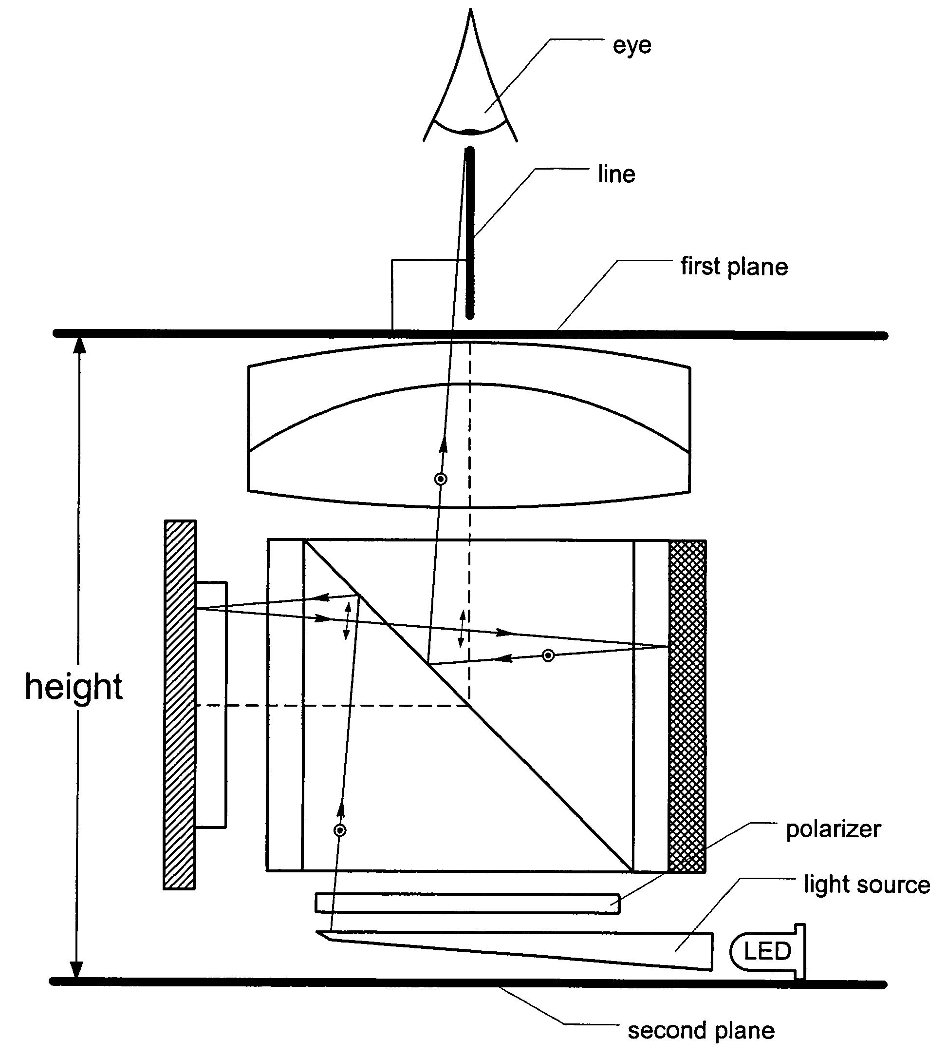
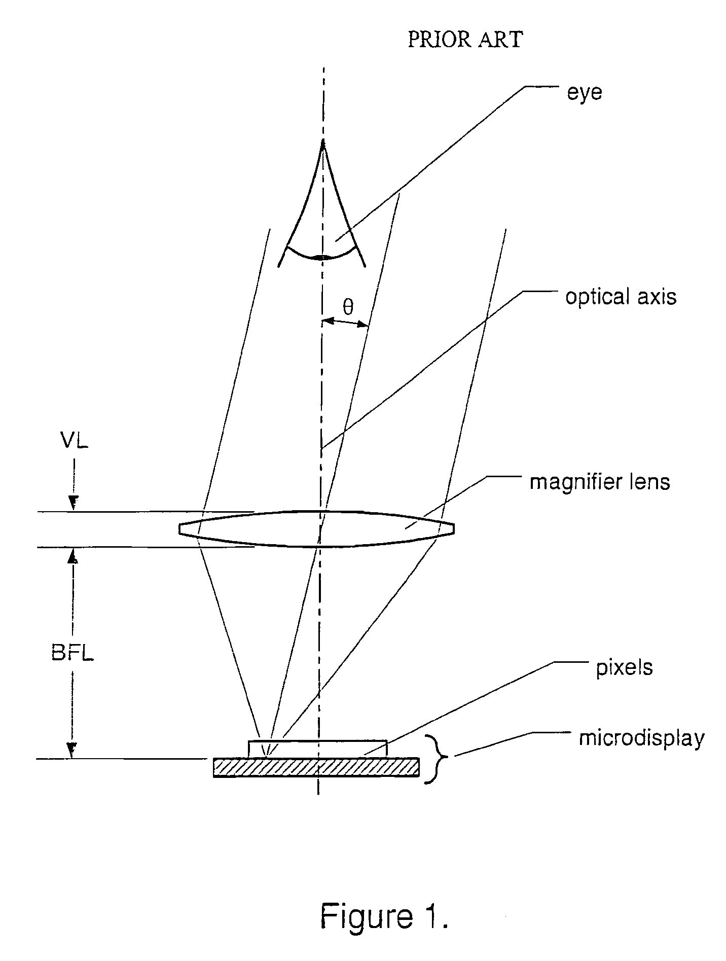
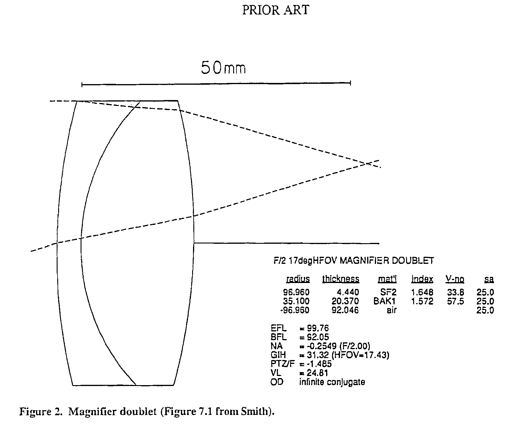
[0033]FIG. 7 shows an electronic viewfinder 20 of the present invention. It uses an achromatic doublet magnifier 22 very similar to that described with reference to FIG. 2. However, through the use of a polarizing beam splitter (PBS) 24, the optical path between the magnifier lens 22 and a microdisplay 26 is folded, reducing the effective height of the viewfinder. A diffuse extended light source 28 provides light that is polarized by a polarizer 30 before it is directed to the PBS 24. Light having (s) polarization thus enters the PBS cube 24 from the light source 28 on the bottom, and, after striking the beam-splitter face, is reflected onto the microdisplay 26. ON pixels on the microdisplay reflect the incident light, rotating its polarization to so that it is transmitted across the beam splitter 24 to a stack 32 including a mirror 34 plus a quarter-wave plate (QWP) 36 on the cube face opposite the microdisplay 26. This stack 32 again rotates the light's polarization, back to , an...

second embodiment

[0034]FIG. 8 shows an electronic viewfinder 40 of the present invention. It is similar to the embodiment of FIG. 7 in using a magnifier 42 of the achromatic doublet form. It accomplishes even greater reduction of height, though, through an even greater degree of folding of the optical path. The illuminator (not shown) now sits in the aperture of the magnifying lens 42, and emits -polarized light through a PBS 44 towards a microdisplay 46. Again, ON pixels on the microdisplay 46 reflect the incident illumination, rotating its polarization to . This -polarized light is reflected by PBS 44 towards a first mirror-plus-QWP stack 48, where its polarization is rotated to and it is reflected towards a second mirror-plus-QWP stack 50, located on the opposite side of the cube. The light's polarization is again rotated (now back to >, and the light is reflected towards the PBS 44, which in turn reflects it upwards to the magnifier 42. In the embodiment described with respect to FIG. 7, the op...

third embodiment

[0036]an electronic viewfinder 60 of the invention is shown in FIG. 9. This embodiment is similar to the embodiment described with reference to FIG. 7, except the flat mirror 34 of FIG. 7 has been replaced by a Mangin mirror 62. The curved Mangin mirror 62 augments the magnifying power of a magnifying lens 64. Using a mirror to provide magnification has some advantages over using a lens: the mirror introduces no chromatic aberration, it introduces less spherical aberration, and it introduces field curvature with a sign opposite to the curvature introduced by a lens.


PUM


Abstract

An electronic viewfinder with a reflective microdisplay and associated optical elements in a design that utilizes one or more folded optical paths to achieve a compact size and volume that may have a dimension of less than 10 millimeters per side. Moreover, the optical design may have an effective focal length that is greater than the spacing of the optical elements from the microdisplay. Various embodiments include a pancake window arrangement with reflective surfaces that are spaced apart from each other and cube beamsplitter eyepieces with folded paths.

Description

CROSS-REFERENCE TO RELATED APPLICATION[0001]This application claims priority from U.S. Provisional Patent Application No. 60 / 542,074 filed Feb. 4, 2004, entitled “Compact Electronic Viewfinder”, the contents of which are incorporated herein by reference.[0002]The present invention relates generally to optical systems such as electronic viewfinders, and more particularly to compact designs for optical systems for electronic viewfinders.BACKGROUND OF THE INVENTION[0003]Most still cameras and video cameras today have viewfinders to allow the user to view a representation of the image to be recorded. While these were originally purely optical in nature, they have increasingly become electronic viewfinders such as are typically provided with modern video cameras. Many digital still cameras also have electronic viewfinders, as do wireless Internet appliances, and head-mounted displays. As is often the case in the consumer electronics industry, there is constant pressure to shrink the size...

Claims


Application Information

Patent Timeline
Patent Type & Authority Patents(United States)
IPC IPC(8): G02B27/14G09G5/00G02B23/14G02B27/28G03B13/02H04N5/225
CPCG02B23/14G02B27/283G03B13/02H04N5/2254H04N23/55
Inventor WEISSMAN, PAULHANDSCHY, MARK A.
Owner CITIZEN FINETECH MIYOTA CO LTD
Why Eureka
Try Eureka