Image observing apparatus

a technology of image observation and apparatus, applied in the field of image observation apparatus, can solve the problems of difficult manufacturing, easy occurrence of pixel defects, and complicated configuration

Inactive Publication Date: 2007-04-17
CANON KK
View PDF7 Cites 10 Cited by
  • Summary
  • Abstract
  • Description
  • Claims
  • Application Information

AI Technical Summary

Problems solved by technology

These types of elements are, as necessary pixels must be all built up in the elements, easy to have occurrence of a pixel defect and hard to be manufactured.
H11-095144, two scanning devices for the horizontal direction and the vertical direction are employed, and consequently the configuration becomes complicated.

Method used


Image

  • Image observing apparatus
  • Image observing apparatus
  • Image observing apparatus

Examples


Embodiment Construction

[0017]Embodiments of an image observing apparatus according to the present invention will hereinafter be described with reference to FIGS. 1 and 2.

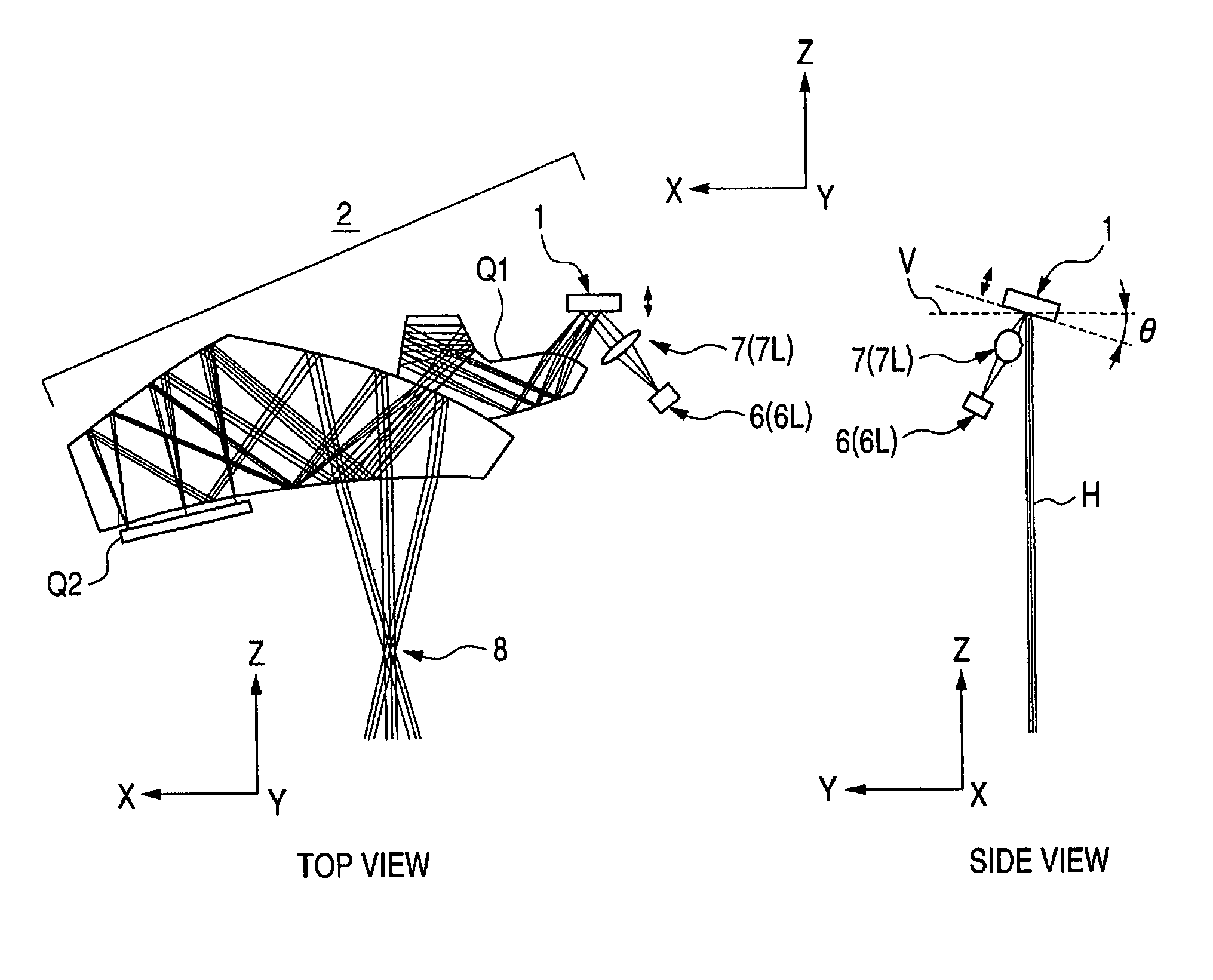
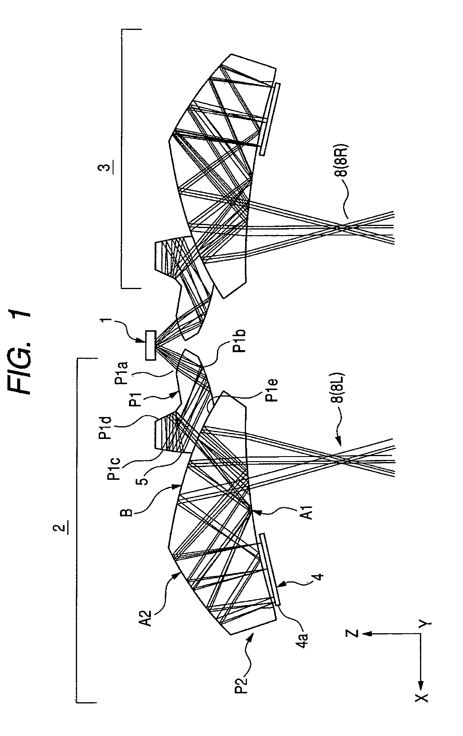
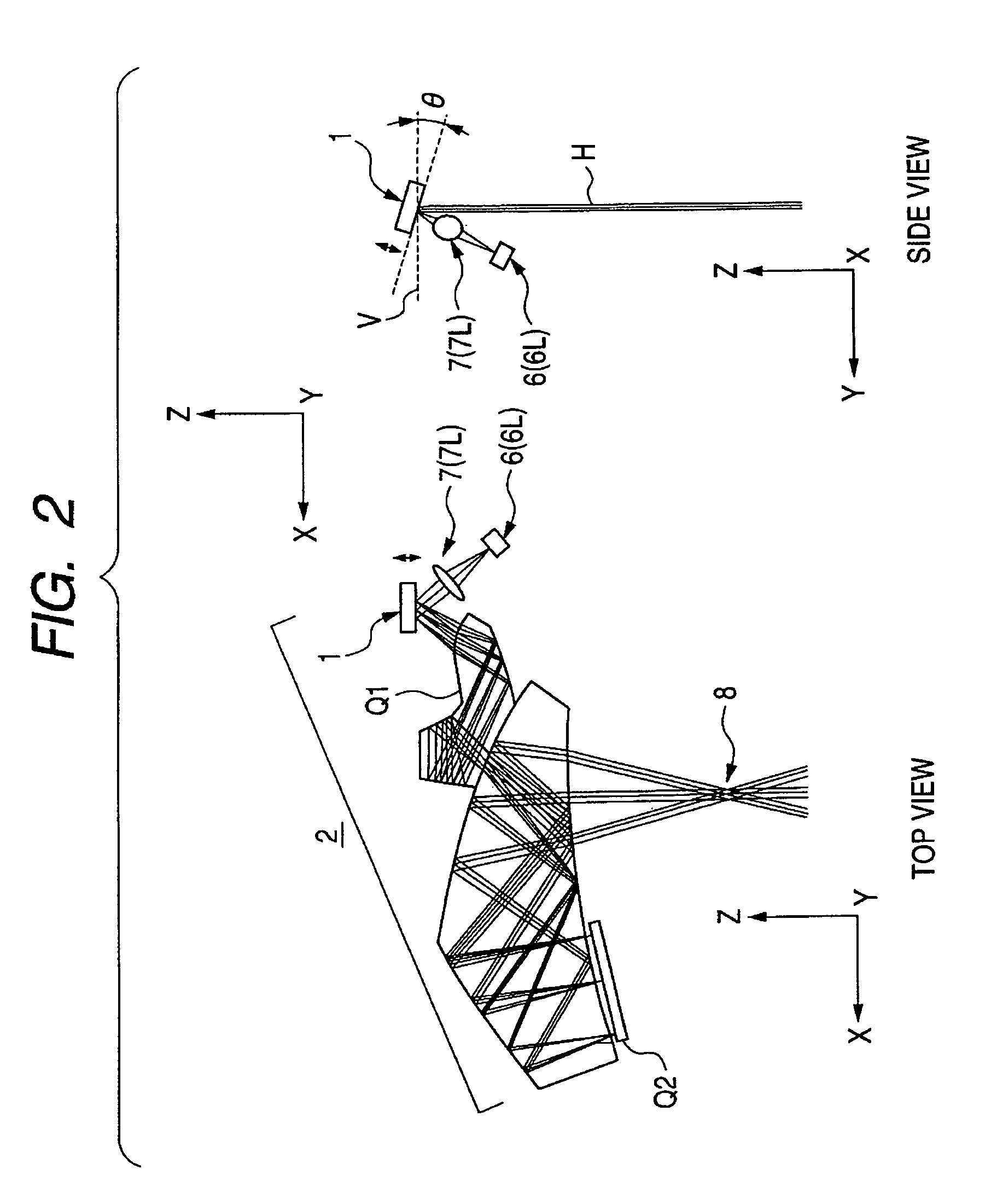
[0018]Referring to FIGS. 1 and 2, the reference numeral 1 demotes a two-dimensional scanning mirror (scanning mirror), 2 denotes an optical system for a left eye, 3 denotes an optical system for a right eye, 6 denotes a light source, 7 denotes a collimator lens, and 8 (8L, 8R) represent exit pupils of the optical systems 2, 3 respectively, which are defined as positions where the right and left eyes of an observer should be disposed.

[0019]FIG. 1 is a sectional view (a top view) showing optical paths from the scanning mirror 1 to the exit pupils 8 (8L, 8R) for the right and left eyes. FIG. 2 is a sectional view (a top view and a side view) of an optical path from the light source 6L for the left eye to the exit pupil 8L of the optical system 2 for the left eye.

[0020]The light source 6 is constructed of, though not illustrated, luminescent ...


PUM


Abstract

An image observing apparatus has two light sources, a scanning mirror upon which light beams from the two light sources are incident in common, and two optical systems. The two optical systems respectively lead the light beams emitted from the two light sources and scanned by the scanning mirror to the right and left eyes of an observer. The light beams emitted respectively from the two light sources are scanned by the scanning mirror and form two-dimensional images for the right and left eyes on predetermined surfaces. Central field angle principal rays emitted respectively from the two light sources and reflected by the scanning mirror, exist on the same plane. Then, an angle made by the scanning mirror and by a surface vertical to the central field angle principal rays emerging from the two optical systems, is set so as to fall within a predetermined range.

Description

BACKGROUND OF THE INVENTION[0001]1. Field of the Invention[0002]The present invention relates to an image observing apparatus suited to a head mounted display (HMD) and the like.[0003]2. Related Background Art[0004]At the present, a display device employed for the HMD is exemplified such as a transparent type liquid crystal element, a reflection type liquid crystal element, or an EL (Electroluminescence) element. These types of elements are, as necessary pixels must be all built up in the elements, easy to have occurrence of a pixel defect and hard to be manufactured.[0005]Further, a display device is proposed in U.S. Pat. No. 5,467,104, wherein an image is displayed and observed by employing a scanning device without using a two-dimensional display device such as the liquid crystal element and the EL element.[0006]U.S. Pat. No. 5,467,104 discloses a scan type image display device that scans light beams assuming respective colors of Red, Green, and Blue in a horizontal direction and...

Claims


Application Information

Patent Timeline
Patent Type & Authority Patents(United States)
IPC IPC(8): G02B27/14G09G5/00
CPCG02B17/0848G02B17/086G02B27/017G02B27/0172G02B2027/0123G02B2027/0132
Inventor YAMAZAKI, SHOICHI
Owner CANON KK
Why Eureka
Try Eureka