
Percussion drill bit and a regrindable cemented carbide button therefor

a drill bit and button technology, applied in drill bits, earthwork drilling and mining, cutting machines, etc., can solve the problems of premature wear, slow penetration rate, and non-enhanced cemented carbide provided, and achieve the effect of increasing penetration rate and prolonging the life of the bi

Inactive Publication Date: 2007-04-24
SANDVIK AB
View PDF7 Cites 31 Cited by
  • Summary
  • Abstract
  • Description
  • Claims
  • Application Information

AI Technical Summary

Benefits of technology

[0004]An object of the present invention is to provide a drill bit for percussive drilling, wherein the life of the bit is extended.
[0006]Still another object of the present invention is to provide a regrindable cemented carbide button for percussive drilling, which makes the pressing tool more durable.
[0007]Still another object of the present invention is to provide a regrindable cemented carbide button for percussive drilling, which button can be reground in a stable manner.
[0008]Still another object of the present invention is to provide a regrindable cemented carbide button for percussive drilling, which button can be reground in a stable manner.

Problems solved by technology

Known drill bits that are provided with non-enhanced cemented carbide buttons such as disclosed in EP-B1-886 715 have disadvantages in that they wear prematurely and have slow penetration rates.
Furthermore regrinding of conventional buttons becomes unstable.

Method used


Image

  • Percussion drill bit and a regrindable cemented carbide button therefor
  • Percussion drill bit and a regrindable cemented carbide button therefor
  • Percussion drill bit and a regrindable cemented carbide button therefor

Examples


Embodiment Construction

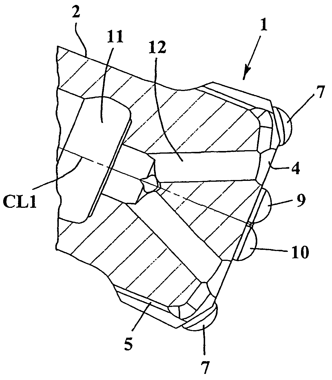
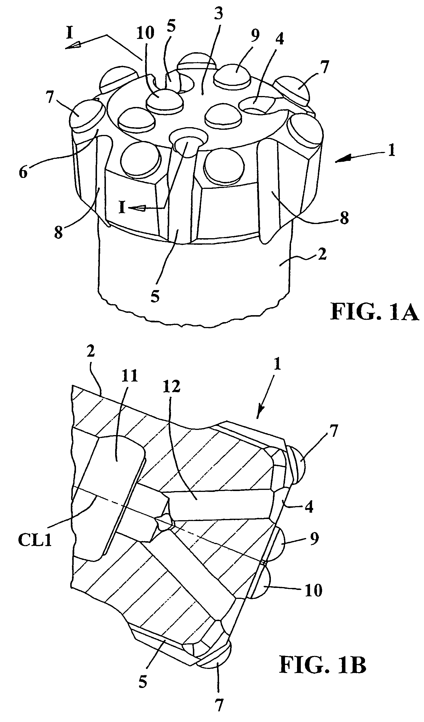
[0016]In FIGS. 1A and 1B a rock drill bit is shown, which in a usual manner comprises a body and cemented carbide buttons. The body comprises a substantially cylindrical head portion 1 and a more slender shaft 2. The body of the drill bit is made of steel. The head portion 1 comprises a front surface or a front side designated with 3, in which a number of buttons are mounted. The front surface may be substantially planar. A first surface portion 6, located between the front surface 3 and the periphery of the head portion, is conically shaped. On this conical surface 6 are provided a number of first buttons or gauge row buttons 7 forming a peripheral ring on the head portion. The buttons 7 in this case project somewhat outside the periphery of the head portion in order to machine a hole during drilling which has a somewhat bigger diameter than the very head portion. Chipways or recesses 8 are provided in areas between adjacent peripheral buttons 7, through which flush medium can pass...


PUM


Abstract

A percussion drill bit for drilling a bore includes a drill body having a connecting section at a rear end thereof for connection to a percussive unit, and a plurality of cemented carbide buttons embedded in a front end of the drill body. Each button comprises a cemented carbide body having a rear mounting portion embedded in the drill body, and a front end protruding from the drill body. The front end of the cemented carbide button is substantially semi-spherically curved and defined by a radius whose origin is disposed axially rearwardly of a plane through the largest diameter of the button. The button projects from the drill bit body a distance which is not less than 50% of the button diameter. A conical intermediate surface forms, in cross-section, an acute angle of about 13–19° with an envelope surface of the rear mounting portion.

Description

TECHNICAL BACKGROUND[0001]The present invention relates to a percussion drill bit for drilling bores in rock. A typical percussion drill bit comprises a steel drill body, means at one end of the drill body for connecting the bit to a percussive unit such as a drill string for a jack hammer or a down-the-hole hammer, and a plurality of buttons embedded in the other end of the drill body. The present invention also relates to a regrind able button for use in said drill bit.[0002]Each button comprises a cemented carbide body having a rear mounting portion embedded in the drill body and a front end protruding from the drill body.[0003]Known drill bits that are provided with non-enhanced cemented carbide buttons such as disclosed in EP-B1-886 715 have disadvantages in that they wear prematurely and have slow penetration rates. Furthermore regrinding of conventional buttons becomes unstable. Other known drill bits are shown in U.S. Pat. No. 3,788,409 and U.S. Pat. No. 6,220,376.OBJECTS OF...

Claims


Application Information

Patent Timeline
Patent Type & Authority Patents(United States)
IPC IPC(8): E21B10/36E21B10/56
CPCE21B10/56
Inventor BJORK, FREDRIK
Owner SANDVIK AB
Learn More