Welded joints for rotary-vibratory drills having reduced stress

a technology of vibration drill and joint, which is applied in the direction of drilling tools, drilling machines and methods, boring/drilling apparatus, etc., can solve the problems of inability to develop suitable drill tooling, extremely high alternating force within the drill pipe, and failure to completely succeed, so as to reduce the prospect of losing expensive drills down the drill hole, the structure of the drill assembly is actually simplified, and the drill string life is considerably enhanced

Inactive Publication Date: 2007-11-06
ROUSSY RAYMOND JOSEPH
View PDF4 Cites 0 Cited by
  • Summary
  • Abstract
  • Description
  • Claims
  • Application Information

AI Technical Summary

Benefits of technology

[0017]The invention offers significant advantages compared to the prior art. Effectively the life of the drill string is considerably enhanced compared with prior art connection methods. Furthermore, this is done economically compared to alternative measures such as stress relieving. The prospect of losing expensive drills down a drill hole is significantly reduced. At the same time, the structure of the drill assembly is actually simplified compared to some of the prior art.

Problems solved by technology

One of the major problems associated with sonic drilling machines in the past has been the failure to develop suitable drill tooling.
Extremely high alternating forces are generated within the drill pipe.
This was not completely successful because the threads reduced the cross-sectional area of the pipe and simultaneously acted as a point of stress concentration as suggested above.
However, it was then realized that the drill pipe stains or elongates and contracts the same amount in resonance regardless of its thickness.
The greater cross section simply increases the force which must be transmitted by the joint, leading to failure at the threads.
These welds however do not long withstand the fatigue loading conditions and high stress concentrations encountered in sonic drilling.
However, the problem encountered in that instance is not analogous to the difficulties encountered in sonic drilling and therefore does not suggest a solution to the problem.
However, although a vast improvement over the prior art, some problems remained.
In particular, the life of the drills has been shorter than considered desirable.
Analysis has shown that the problem is caused by the weld puddle at the bottom of the V-shaped slot in the drill pipe.
As this weld puddle cools, it shrinks and causes high tensile stresses that this location.
When the pipe is then vibrated, cracks form around these weld puddles.
Eventually the cracks start to propagate until they meet each other and the pipe fails completely.
If this happens in a deep hole, then the length of pipe below the fracture point is lost at considerable expense.
However this is not very practical since stress relief furnaces are usually not long enough.
Furthermore, only a few pieces could be done at one time since the rods and casing would go too far out of round unless they are properly supported.
Consequently such stress relieving would make the parts too expensive.

Method used


Image

  • Welded joints for rotary-vibratory drills having reduced stress
  • Welded joints for rotary-vibratory drills having reduced stress
  • Welded joints for rotary-vibratory drills having reduced stress

Examples


Embodiment Construction

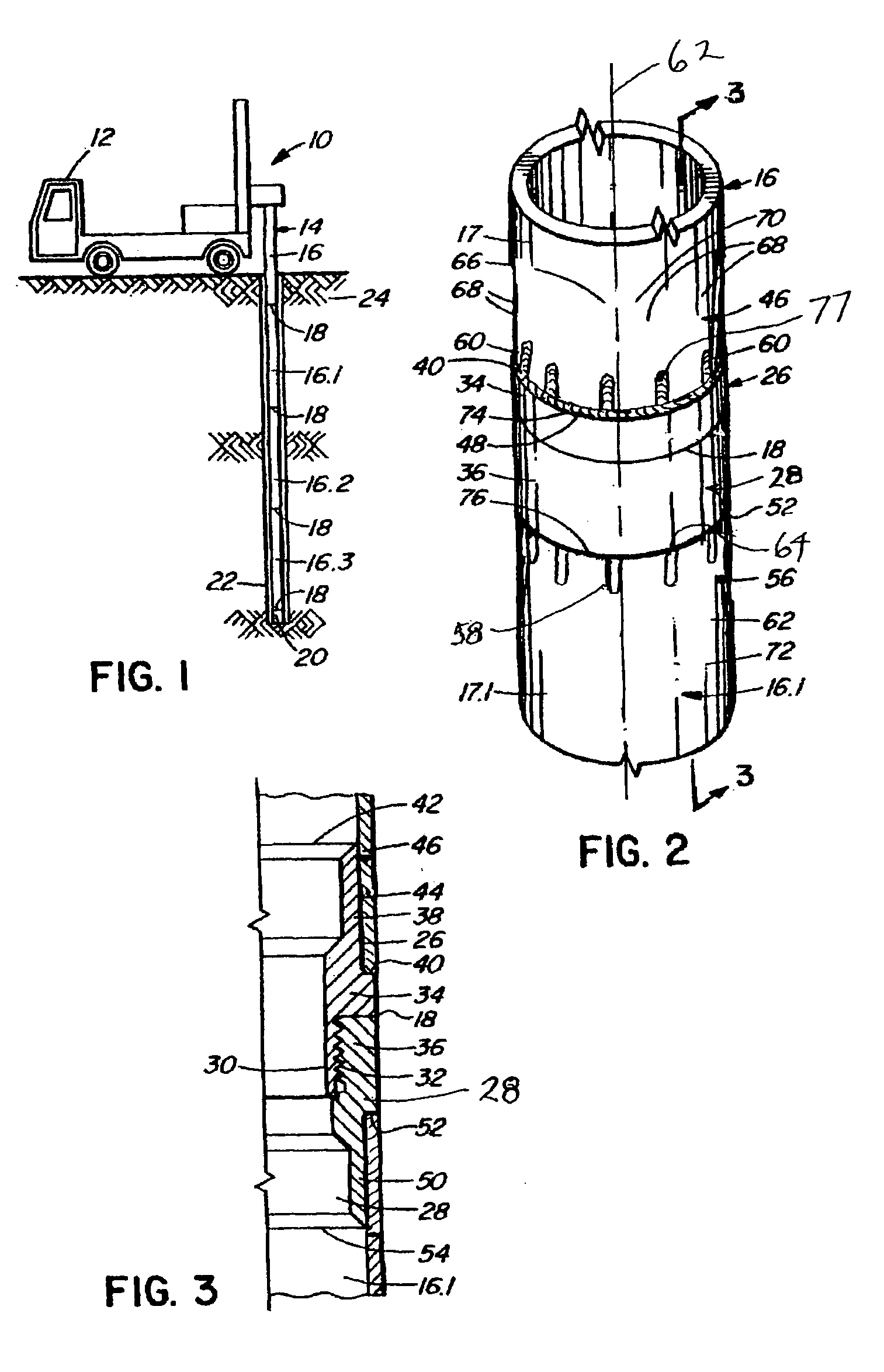
[0023]Referring to the drawings, FIG. 1 shows a sonic drilling rig 10 which, in this example, is mounted on the back of a truck 12. As mentioned above, sonic drills are combination rotary and vibratory drills where the vibrations are in the sonic range. The drilling rig is conventional and therefore is not described in greater detail.

[0024]The drilling rig is connected to a drill string 14 which includes a plurality of drill pipe assemblies 16, 16.1, 16.2 and 16.3 with a drilling tool 20 at the bottom end for drilling a drill hole 22 through overburden 24 or some other geological structure. The drill pipe assemblies are connected together at a series of pipe joints 18.

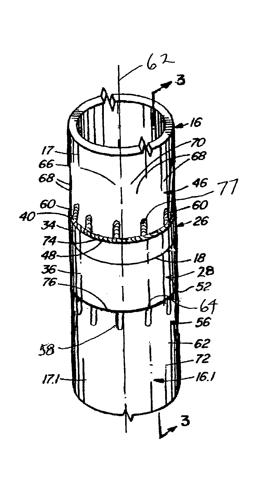
[0025]One of the pipe joints 18 is shown in FIGS. 2 and 3, the others being identical. The joint includes a male threaded connector member 26 which threadedly engages a complementary female threaded connector member 28. As shown best in FIG. 3, the threads 30 of member 26 engage the threads 32 of member 28.

[0026]The me...


PUM


Abstract

A drill string for a rotary-vibratory drill comprises a plurality of drill pipes. Each of the drill pipes has a longitudinal axis and at least one end. A female connector member and a male connector member are between the ends of adjacent said drill pipes, the female connector member having a first portion mating with a first of the adjacent drill pipes and a second portion extending away from the first of the drill pipes. The male connector member has a first portion mating with a second of the adjacent drill pipes and a second portion extending away from the second of the drill pipes, the second portion of the female connector threadedly engaging the second portion of the male connector. One of said each drill pipe and the connectors has a plurality of spaced-apart slots adjacent to the end of the drill pipe and communicating outwardly at the end. The slots are parallel to the longitudinal axis. Each of the connectors is connected to one of the adjacent drill pipes by welding extending about an adjacent said end of the one drill pipe and along the slots.

Description

BACKGROUND OF THE INVENTION[0001]This invention relates to drill pipes for rotary-vibratory drills and, in particular, to joints for the drill pipes.[0002]Rotary-vibratory drills employ a vibratory force superimposed upon a rotary action to accomplish the drilling operation. Sonic drills are rotary-vibratory drills where the vibration is in the sonic range. Sonic drills are used for such applications as drilling through overburden in placer exploration, installing concrete piles, water well drilling, rock drilling for blast holes, for rock coring and for testing soil for levels of contamination.[0003]One of the major problems associated with sonic drilling machines in the past has been the failure to develop suitable drill tooling. Extremely high alternating forces are generated within the drill pipe. Standard drill pipe is designed to withstand the torque developed during rotary drilling, but not the high alternating tensile and compressive loads encountered in sonic drilling. Thes...

Claims


Application Information

Patent Timeline
Patent Type & Authority Patents(United States)
IPC IPC(8): E21B17/16B23B51/00E21B7/24E21B17/042
CPCE21B17/0426E21B7/24
Inventor ROUSSY, RAYMOND JOSEPH
Owner ROUSSY RAYMOND JOSEPH
Why Eureka
Try Eureka