
Elevator

a technology of elevator shaft and elevator shaft, which is applied in the direction of elevator, building lift, mine lift, etc., can solve the problems of limiting the freedom of choice in elevator lay-out solutions, limiting the application area of elevator concept without machine room, and difficult mounting of hoisting machines in elevator shafts

Inactive Publication Date: 2007-04-24
KONE CORP
View PDF13 Cites 34 Cited by
  • Summary
  • Abstract
  • Description
  • Claims
  • Application Information

AI Technical Summary

Benefits of technology

[0009]Using a small traction sheave, a very compact elevator and / or elevator machine is achieved
[0010]A good traction sheave grip, which is achieved in particular by using Double Wrap roping, and lightweight components allow the weight of the elevator car to be considerably reduced

Problems solved by technology

In these basically good elevator solutions, the space required by the hoisting machine limits the freedom of choice in elevator lay-out solutions.
In a traction sheave elevator without machine room, mounting the hoisting machine in the elevator shaft is often difficult, especially in a solution with machine above, because the hoisting machine is a sizeable body of considerable weight.
Especially in the case of larger loads, speeds and / or hoisting heights, the size and weight of the machine are a problem regarding installation, even so much so that the required machine size and weight have in practice limited the sphere of application of the concept of elevator without machine room or at least retarded the introduction of said concept in larger elevators.
In modernization of elevators, the space available in the elevator shaft often limits the area of application of the concept of elevator without machine room.
In many cases, especially when hydraulic elevators are modernized or replaced, it is not practical to apply the concept of roped elevator without machine room due to insufficient space in the shaft, especially in a case where the hydraulic elevator solution to be modernized / replaced has no counterweight.
A disadvantage with elevators provided with a counterweight is the cost of the counterweight and the space it requires in the shaft.
Drum elevators, which are nowadays rarely used, have the drawbacks of requiring heavy and complex hoisting machines with a high power consumption.
Prior-art elevator solutions without counterweight are exotic, and no adequate solutions are known.
Before, it has not been technically or economically reasonable to make elevators without a counterweight.
In prior-art elevator solutions without counterweight, the tensioning of the hoisting rope is implemented using a weight or spring, and this is not an attractive approach to implementing the tensioning of the hoisting rope.
Another problem with elevator solutions without counterweight, when long ropes are used e.g. due to a large hoisting height or a large rope length required by high suspension ratios, is the compensation of the elongation of the ropes and the fact that, due to rope elongation, the friction between the traction sheave and the hoisting ropes is insufficient for the operation of the elevator.
This can not necessarily be achieved using a spring or a simple lever.

Method used


Image

  • Elevator
  • Elevator
  • Elevator

Examples


Embodiment Construction

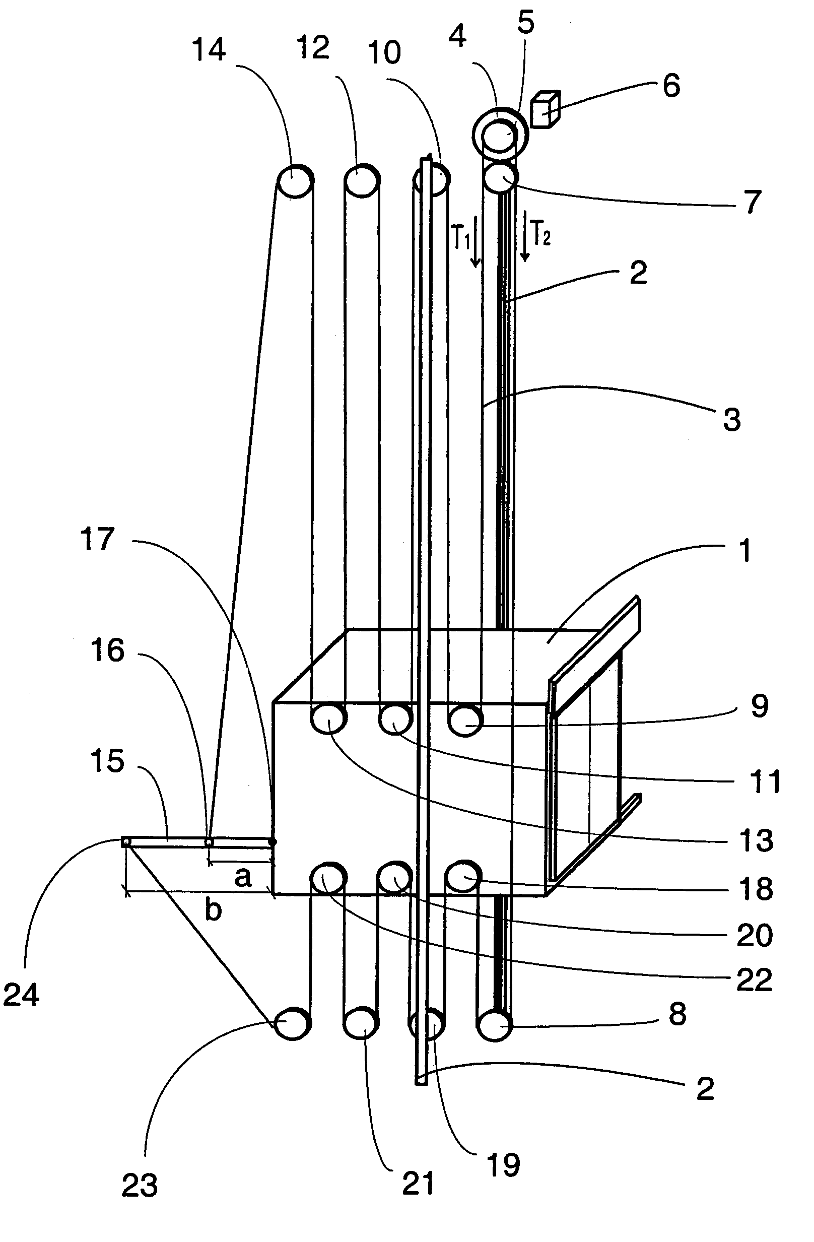
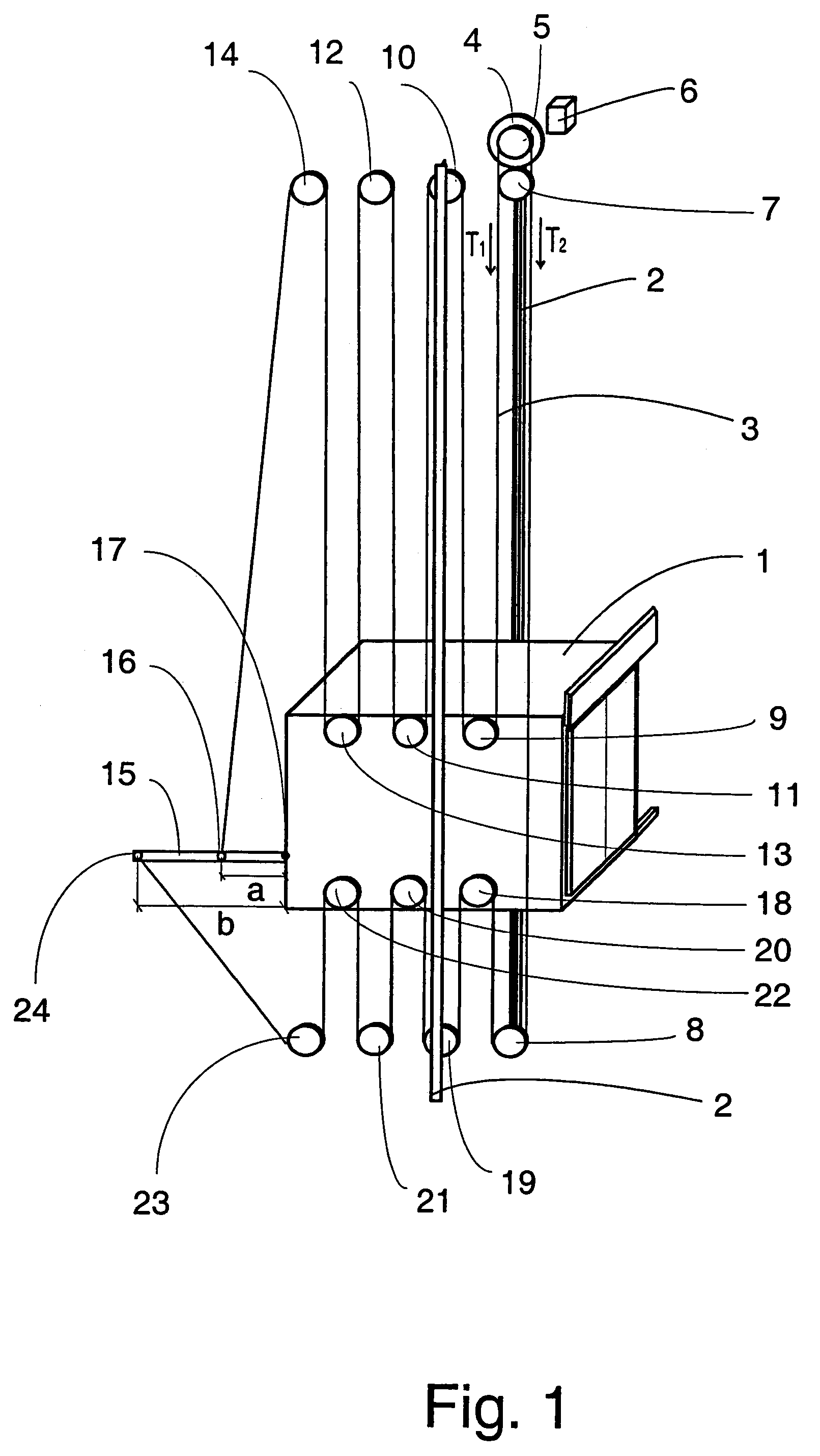
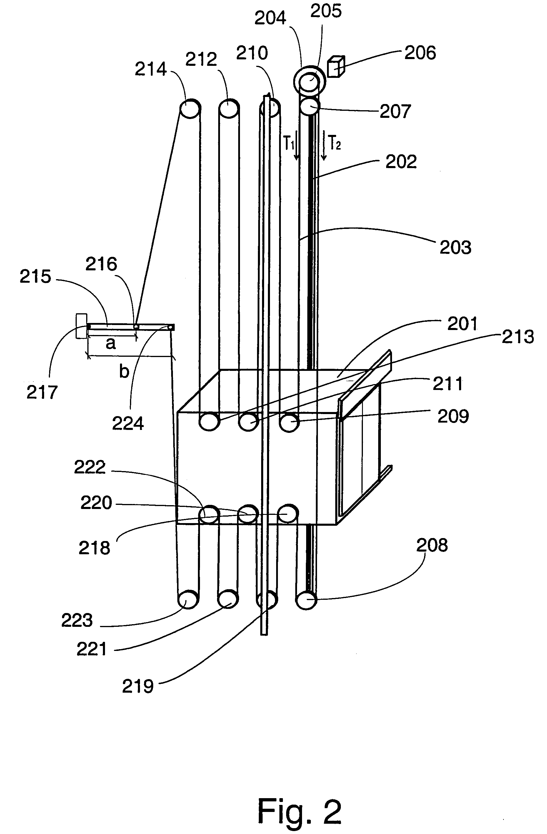
[0059]FIG. 1 presents a diagrammatic illustration of the structure of an elevator according to the invention. The elevator is preferably an elevator without machine room, with a drive machine 4 placed in an elevator shaft. The elevator shown in the figure is a traction sheave elevator without counterweight and with machine above. The passage of the hoisting ropes 3 of the elevator is as follows: One end of the ropes is immovably fixed to a fixing point 16 on a lever 15 fastened to the elevator car 1, said fixing point being located at a distance a from the pivot 17 connecting the lever to the elevator car 1. In FIG. 1, the lever 15 is thus pivoted on the elevator car 1 at fixing point 17. From fixing point 16, the hoisting ropes 3 run upwards to a diverting pulley 14 placed in the upper part of the elevator shaft above the elevator car 1, from which diverting pulley the ropes go further downwards to a diverting pulley 13 on the elevator car, and from this diverting pulley 13 the rop...


PUM


Abstract

An elevator in which the elevator car is suspended by means of hoisting ropes consisting of a single rope or several parallel ropes, said elevator having a traction sheave which moves the elevator car by means of the hoisting ropes. The elevator has rope portions of the hoisting ropes going upwards and downwards from the elevator car, and the rope portions going upwards from the elevator car are under a first rope tension (T1) which is greater than a second rope tension (T2), which is the rope tension of the rope portions going downwards from the elevator car, and that the elevator comprises a compensating system for keeping the ratio (T1 / T2) between the first and the second rope tensions substantially constant.

Description

[0001]This application is a continuation of, and claims priority under 35 U.S.C. §120 and 35 U.S.C. §365(c) from, PCT International Application No. PCT / FI2003 / 000714 which has an International filing date of Oct. 1, 2003, which designated the United States of America, and FINLAND Application Priority Number 20030153 filed Jan. 31, 2003 the entire contents of all of which are hereby incorporated herein by reference.[0002]The present invention relates generally to an elevator.BACKGROUND OF THE INVENTION[0003]One of the objectives in elevator development work is to achieve efficient and economical utilization of building space. In recent years, this development work has produced various elevator solutions without machine room, among other things. Good examples of elevators without machine room are disclosed in specifications EP 0 631 967 (A1) and EP 0 631 968. The elevators described in these specifications are fairly efficient in respect of space utilization as they have made it possi...

Claims


Application Information

Patent Timeline
Patent Type & Authority Patents(United States)
IPC IPC(8): B66B11/08B66B7/10B66B11/00
CPCB66B7/10B66B11/008B66B11/007B66B19/007B66B11/00B66B11/06B66B11/08
Inventor AULANKO, ESKOMUSTALAHTI, JORMA
Owner KONE CORP
Learn More