Modular storage and dispensing assembly

a technology for dispensing assembly and storage, which is applied in the direction of racks, cabinets, show hangers, etc., can solve the problems of difficult assembly of display racks or assemblies, failure to provide the desired rigidity of assembled modules, and loss, etc., and achieves easy construction, easy to increase or decrease the overall size, and economic effect of manufactur

Inactive Publication Date: 2007-04-24
EXELL PROD
View PDF10 Cites 80 Cited by
  • Summary
  • Abstract
  • Description
  • Claims
  • Application Information

AI Technical Summary

Benefits of technology

[0012]An object of the present invention is to provide an improved storage and display assembly for objects, such as cans.
[0014]Another object of the present invention is to provide an improved modular storage and dispensing assembly which is economical to manufacture, easy to construct, and which permits one to readily increase or decrease the overall size of the modular storage and dispensing assembly without detracting from its intended use.

Problems solved by technology

Such separate elements, however, often become lost during shipment, and fail to provide the desired rigidity to the assembled modules.
However, the use of such connectors have created problems in the manufacture of such display racks or assemblies, have resulted in weak or loose connections, or have made such display racks or assemblies difficult to assemble.
In addition, problems have been encountered in floors or tracks of many of the prior art display racks or assemblies in that the floor or tracks become sticky or clammy due to condensation, garbage, spillage and the like dropping on the floors or tracks.
Thus, movement of articles through the display racks or assemblies are impeded, especially in gravity fed display racks or assemblies.

Method used


Image

  • Modular storage and dispensing assembly
  • Modular storage and dispensing assembly
  • Modular storage and dispensing assembly

Examples


Embodiment Construction

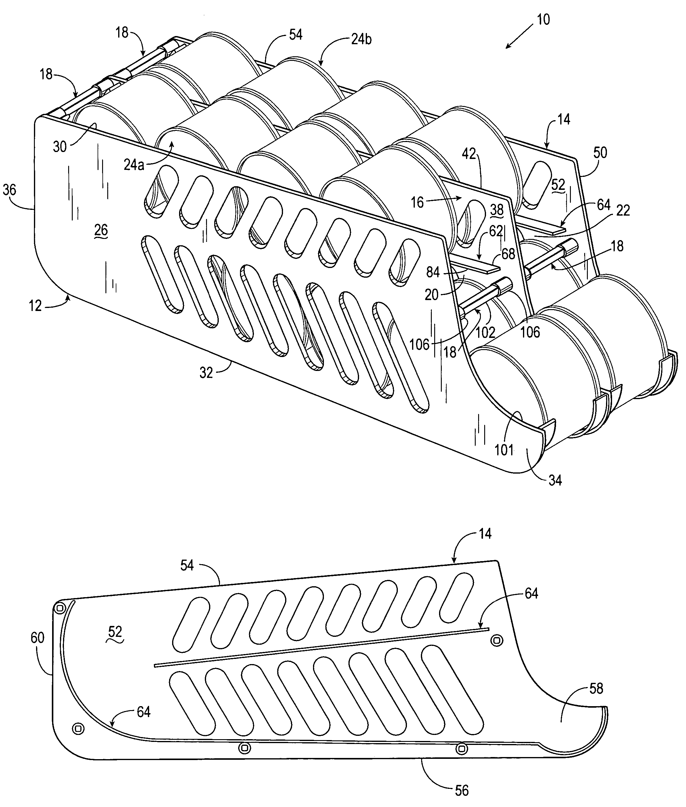
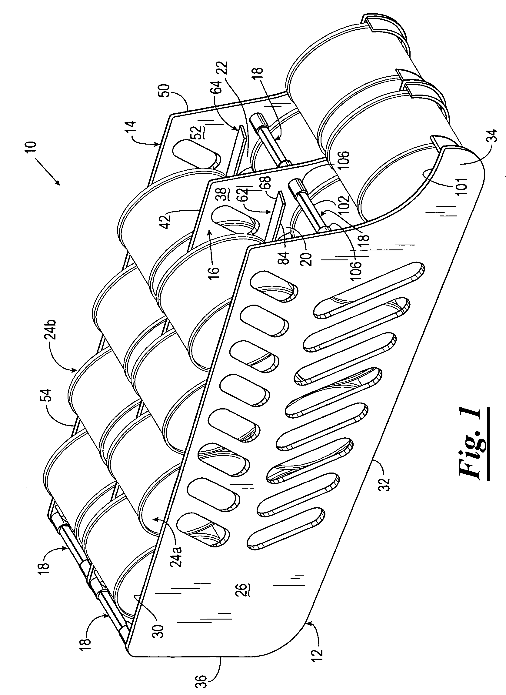
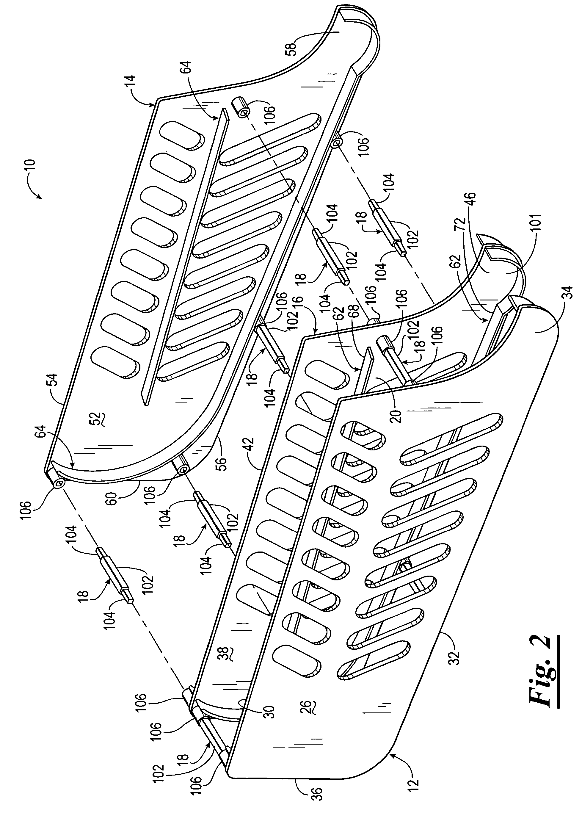
[0022]Referring now to the drawings, and more particularly to FIGS. 1 and 2, shown therein is a modular storage and dispensing assembly 10 constructed in accordance with the present invention. The modular storage and dispensing assembly 10 includes a first panel 12, a second panel 14, a medial panel 16 and a plurality of connector assemblies 18 for connecting the medial panel 16 to the first and second panels 12 and 14, respectively. The connection of the first panel 12 to the medial panel 16 provides the modular storage and dispensing assembly 10 with a first chute 20; and the connection of the second panel 14 to the medial panel 16 provides the modular storage and dispensing assembly 10 with a second chute 22. The first and second chutes 20 and 22 are sized and configured to store a plurality of objects, such as cans 24a and 24b, which can be selectively dispensed therefrom. It should be understood that the unique design of the modular storage and dispensing assembly 10 enables on...


PUM


Abstract

A modular storage and dispensing assembly for storing and selectively dispensing objects, such as cans, includes a plurality of panels and a connector assembly for connecting adjacently disposed panels such that a chute is formed between each of the adjacently disposed panels. A rail assembly is provided in each chute for defining a travel path through the chute. The rail assembly includes an upper rail and a lower rail, each being supported by adjacently disposed panels such that the upper rails in the chute are spatially disposed and in a facing relationship and the lower rails in the chute are also spatially disposed and in a facing relationship. The upper rails each have a first end and a second end and are sloped in a downward direction from their first end to their respective second ends. The lower rails each have an arcuate shaped second end, the lower rails and their arcuate second ends being disposed a distance from the upper rails such that objects moving along the travel path of the chute are provided with a smooth transition from the upper rails to the lower rails. The modular storage and dispensing assembly also is provided with a stop assembly for restraining an object therein while permitting the object to be removed therefrom.

Description

CROSS REFERENCE TO RELATED APPLICATIONS[0001]This application claims benefit of U.S. Provisional Application 60 / 528,615, filed Dec. 11, 2003, which is incorporated herein by by reference in its entirety.STATEMENT REGARDING FEDERALLY SPONSORED RESEARCH OR DEVELOPMENT [0002]Not applicable.BACKGROUND OF THE INVENTION[0003]1. Field of the Invention[0004]The present invention relates generally to a storage and dispensing assembly, and more particularly, but not by way of limitation, to a modular storage and dispensing assembly for cans.[0005]2. Brief Description of Related Art[0006]Display racks or assemblies for supporting and displaying articles on shelves or in confined areas, such as a refrigerator or a cold storage unit, are well known. Generally, such display racks or assemblies are gravity fed or utilize a spring mechanism to move articles along one or more travel paths of the display racks or assemblies.[0007]Because there is often wasted space on at least one side of the displa...

Claims


Application Information

Patent Timeline
Patent Type & Authority Patents(United States)
IPC IPC(8): A47F1/04A47F1/08A47F7/28
CPCA47F1/087A47F7/28
Inventor MEDCALF, MERLE D.MEDCALF, MICHAEL D.
Owner EXELL PROD
Why Eureka
Try Eureka