Chuck assembly

Active Publication Date: 2007-04-24
YUKIWA SEIKO
View PDF29 Cites 7 Cited by
  • Summary
  • Abstract
  • Description
  • Claims
  • Application Information

AI Technical Summary

Benefits of technology

[0007]Accordingly, in order to overcome the above-noted defects, an object of the present invention is to provide an excellent chuck assembly that is superior in assembling workability, may be produced in low cost and is superior in mass-production property, in which a convex and concave engaging means is provided between a rotary sleeve and a ring member (shape holding ring), the ring member (shape holding ring) and the rotary sleeve are engaged with each other by the convex and concave engaging means so that the ring member (shape holding ring) may be retained to the rotary sleeve while being prevented from the rotary sleeve by a so-called one action.
[0009]According to the first aspect of the invention, there is provided a chuck assembly in which a rotary sleeve 2 provided on a body 1 is rotated, jaws 4 engaged with rotary nuts 3 are moved back and forth to be opened and closed by the rotation of the rotary nut 3 rotated together with the rotary sleeve 2 and a tool is clamped by the jaws 4, characterized in that a ring member 8 is provided in the rotary nuts 3, a convex and concave engaging means is provided between the ring member 8 and the rotary sleeve 2, and the ring member 8 and the rotary sleeve 2 are retained and prevented from falling apart from each other by the convex and concave engaging means.
[0019]Accordingly, according to the present invention, the manufacturing process is simplified, and furthermore, the assembling workability is enhanced to extremely simplify the manufacturing process. It is possible to provide a chuck assembly that is superior in mass-production property and cost performance.

Problems solved by technology

However, it is troublesome to arrange the stop ring 36.

Method used


Image

  • Chuck assembly
  • Chuck assembly
  • Chuck assembly

Examples


first embodiment

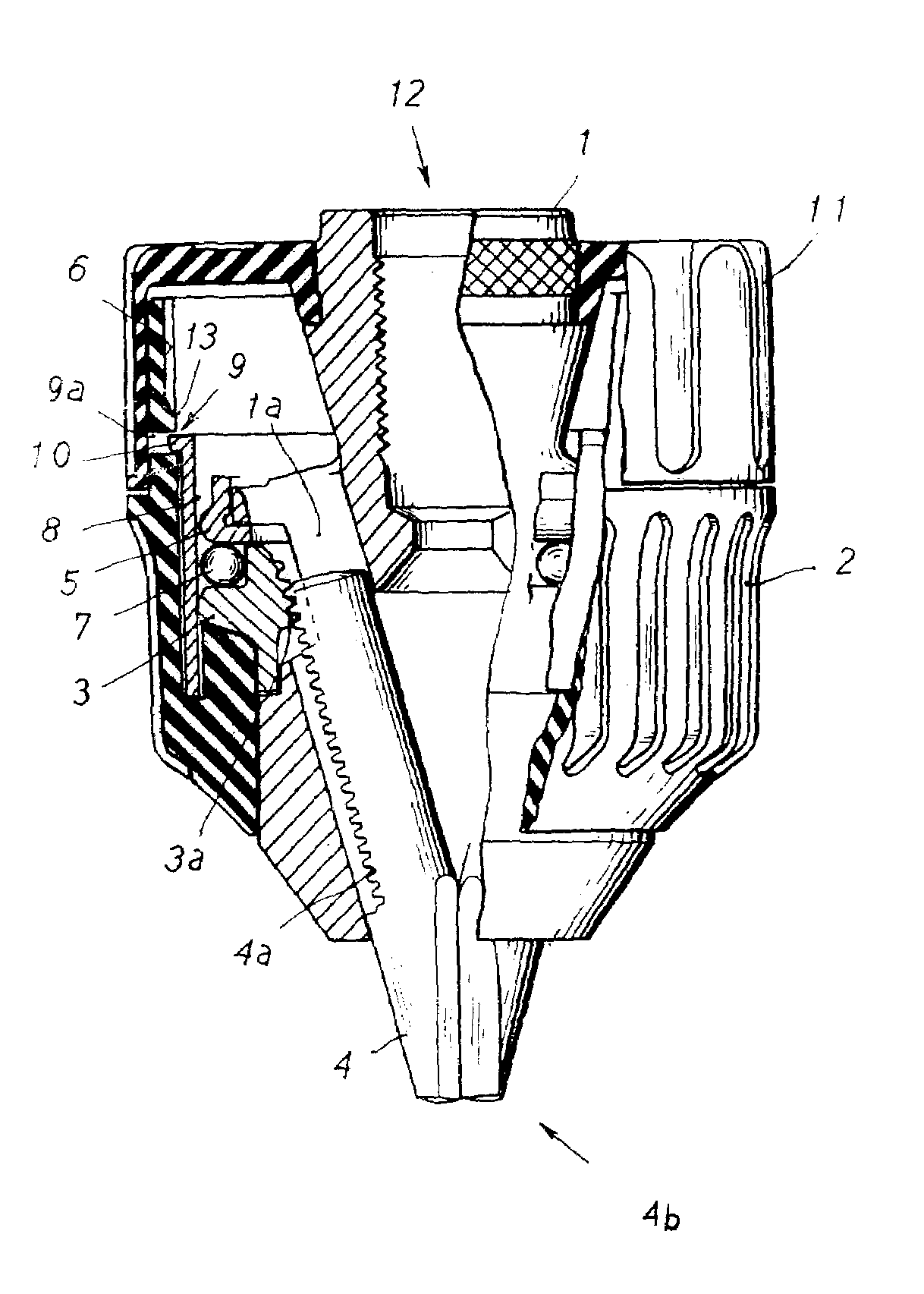
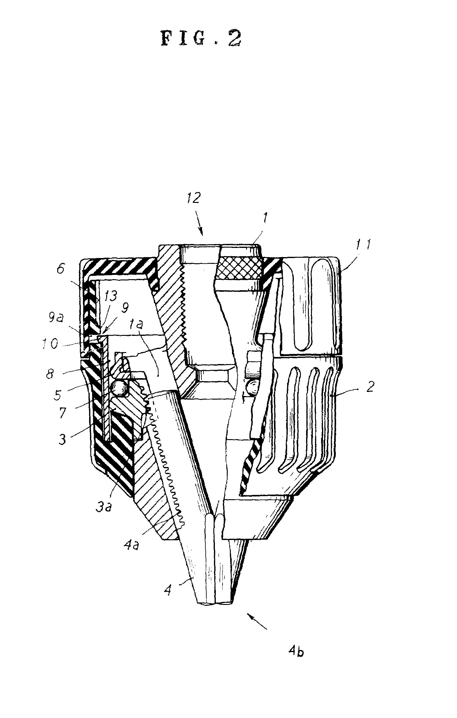
[0027]the present invention will now be described with reference to FIGS. 2, 3 and 4.

[0028]The first embodiment is directed to a chuck assembly in which a rotary sleeve 2 provided on a body 1 is rotated, jaws 4 engaged with rotary nuts 3 are moved back and forth to be opened and closed by the rotation of the rotary nuts 3 rotated together with the rotary sleeve 2 to thereby hold a tool by the jaws 4. A ring member 8 is provided on the rotary nuts 3. A convex and concave engaging means is provided between the ring member 8 and the rotary sleeve 2. The ring member 8 and the rotary sleeve 2 are retained and prevented from falling apart from each other by the convex and concave engaging means.

[0029]Describing the body 1 more specifically, there are provided the three jaws 4 forming a tool clamping portion in their inner circumferential surfaces, passing through slant hole 1a formed in the body 1 and projecting toward a tip end and slanted with respect to an axis of the body 1. Male scre...

second embodiment

[0052]The second embodiment is directed to a chuck assembly in which a rotary sleeve 2 provided on a body 1 is rotated, jaws 4 engaged with rotary nuts 3 are moved back and forth to be opened and closed by the rotation of the rotary nuts 3 rotated together with the rotary sleeve 2 to thereby hold a tool by the jaws 4. A ring member 8 is provided on the rotary nuts 3. A convex and concave engaging means is provided between the ring member 8 and the rotary sleeve 2. The ring member 8 and the rotary sleeve 2 are retained and prevented from falling apart from each other by the convex and concave engaging means.

[0053]Describing the body 1 more specifically, there are provided the three jaws 4 forming a tool clamping portion in their inner circumferential surfaces, passing through slant hole 1a formed in the body 1 and projecting toward a tip end and slanted with respect to an axis of the body 1. Male screw portions 4a are formed on the outer surfaces of the three jaws 4. The rotary nuts ...


PUM


Abstract

To provide an excellent chuck assembly that is superior in assembling workability, may be produced in low cost and is superior in mass-production property, in which a rotary sleeve (2) provided on a body (1) is rotated, jaws (4) engaged with rotary nuts (3) are moved back and forth to be opened and closed by the rotation of the rotary nut (3) rotated together with the rotary sleeve (2) and a tool is clamped by the jaws (4), a ring member (8) is provided in the rotary nuts (3), a convex and concave engaging means is provided between the ring member (8) and the rotary sleeve (2), and the ring member (8 and the rotary sleeve 2 are retained and prevented from falling apart from each other by the convex and concave engaging means.

Description

BACKGROUND OF THE INVENTION[0001]1. Field of the Invention[0002]The present invention relates to a chuck assembly for clamping a tool.[0003]2. Description of the Related Art[0004]As shown in FIG. 1, in a chuck assembly in accordance with, for example, Japanese Patent Application Laid-Open No. Hei 4-365504, a rotary sleeve 32 provided on a body 31 is rotated, jaws 34 engaged with rotary nuts 33 are moved back and forth to be opened and closed by the rotation of the rotary nuts 33 rotated together with the rotary sleeve 32 to thereby clamp the tool by the jaws 34, the rotary nuts 33 are formed into an annular shape with the divided nuts, and a shape holding ring 35 is provided around the rotary nuts 33 for holding an overall shape of the rotary nuts 33 composed of divided nuts attached to an inner circumferential surface of the rotary nuts 33. In this case, reference numeral 37 designates a grip sleeve.[0005]By the way, if the shape holding ring 35 attached to the rotary sleeve 32 for...

Claims


Application Information

Patent Timeline
IPC IPC(8): B23B31/12B23B31/173
CPCB23B31/1238Y10T279/17632Y10S279/902B23B2231/38
Inventor SAKAMAKI, KAZUOSAKAMAKI, AKIRASATO, CHOKICHI
Owner YUKIWA SEIKO
Why Eureka
Try Eureka