Multi-section particle accelerator with controlled beam current

a particle accelerator and beam current technology, applied in accelerators, klystrons, electric discharge tubes, etc., can solve the problems of reducing accelerator efficiency, rf power loss, and not maximizing the power delivered by each feeding waveguide (i.e., in the form of electromagnetic waves), and achieve the effect of reducing or eliminating electromagnetic wave reflections

Inactive Publication Date: 2007-04-24
SCANTECHIBS IP HLDG
View PDF7 Cites 32 Cited by
  • Summary
  • Abstract
  • Description
  • Claims
  • Application Information

AI Technical Summary

Benefits of technology

[0010]Broadly described, the present invention comprises a particle accelerator system with controlled charged particle beam current and methods of operating same. More particularly, the present invention comprises a particle accelerator system which is configurable to operate at different charged particle beam currents while maintaining optimum transfer of electromagnetic power from an RF generator to one or more accelerating sections thereof and reducing or eliminating reflections of electromagnetic waves. The particle accelerator system of the present invention includes at least two accelerating sections and an electromagnetic drive subsystem with portions of the electromagnetic drive subsystem being interposed physically between the accelerating sections. The electromagnetic drive subsystem includes, among other components, a 3 dB waveguide hybrid junction having a coupling window in a wide wall thereof which is shared by the junction's waveguides.
[0011]Advantageously, the particle accelerator system includes movable shorting devices which are positionable in a plurality of positions relative to the accelerator system's longitudinal axis, thereby enabling the coupling coefficients between the accelerator system's feeder waveguides and accelerating sections to be changed by moving the shorting devices into different positions. Because there is only one value of the coupling coefficients between the feeder waveguides and the accelerating sections at which all of the power of the electromagnetic waves of the feeder waveguides is delivered to the accelerating sections without reflections and is maximally utilized for charged particle acceleration for each charged particle beam current at which the particle accelerator system is operated, the movability of the movable shorting devices into a plurality of positions allows optimal setting of the coupling coefficients for operation of the particle accelerator system at any charged particle beam current desired and, hence, allows the particle accelerator system to be operated at a plurality of different charged particle beam currents at peak efficiency. When the coupling coefficients are so optimized, the magnitude of the longitudinal component of the electric field produced at the accelerator system's longitudinal axis is also optimized at a maximum.
[0012]Also advantageously, the particle accelerator system includes an electromagnetic drive subsystem having feeder waveguides which are physically interposed between the system's accelerating sections. A drift tube formed in a common narrow wall shared by the feeder waveguides enables charged particles to travel between the accelerating sections during the system's operation. The common narrow wall shared by the feeder waveguides is also shared by the waveguides of a 3 dB waveguide hybrid junction, thereby causing each of the feeder waveguides to be connected to a respective waveguide of the 3 dB waveguide hybrid junction in a coaxial relationship. By virtue of the feeder waveguides being interposed physically between the system's accelerating sections and by virtue of the coaxial relationship of the feeder waveguides and respective waveguides of the 3 dB waveguide hybrid junction (i.e., thereby requiring no turns, or bends, in the waveguides and, hence, less power loss in the waveguides), the particle accelerator system of the present invention is more compact and more efficient than other known particle accelerator systems.

Problems solved by technology

Unfortunately, reflections of the electromagnetic wave are often produced in the feeding waveguides with the extent of such reflections being dependent, at least in part, upon the coupling coefficients between the feeding waveguides and accelerating sections.
Because the coupling coefficient between each feeding waveguide and respective accelerating section is constant and cannot be changed in the known accelerators for operation at different beam currents, reflections are generated which may travel back to and damage the accelerator's magnetron and, hence, all of the power delivered by each feeding waveguide (i.e., in the form of an electromagnetic wave) is not maximally utilized for particle acceleration.
However, ferrite isolators and circulators are expensive and their use results in RF power losses and, hence, decreased accelerator efficiency.
Thus, by virtue of the coupling window being positioned in the junction's wide wall, the maximal power of the 3 dB waveguide hybrid junction is limited.
Also, the turns or bends in the waveguides that often connect the 3 dB waveguide hybrid junction to the accelerating sections of an accelerator results in the accelerator having larger overall dimensions, making the accelerator less desirable for the applications described above.

Method used


Image

  • Multi-section particle accelerator with controlled beam current
  • Multi-section particle accelerator with controlled beam current
  • Multi-section particle accelerator with controlled beam current

Examples


Embodiment Construction

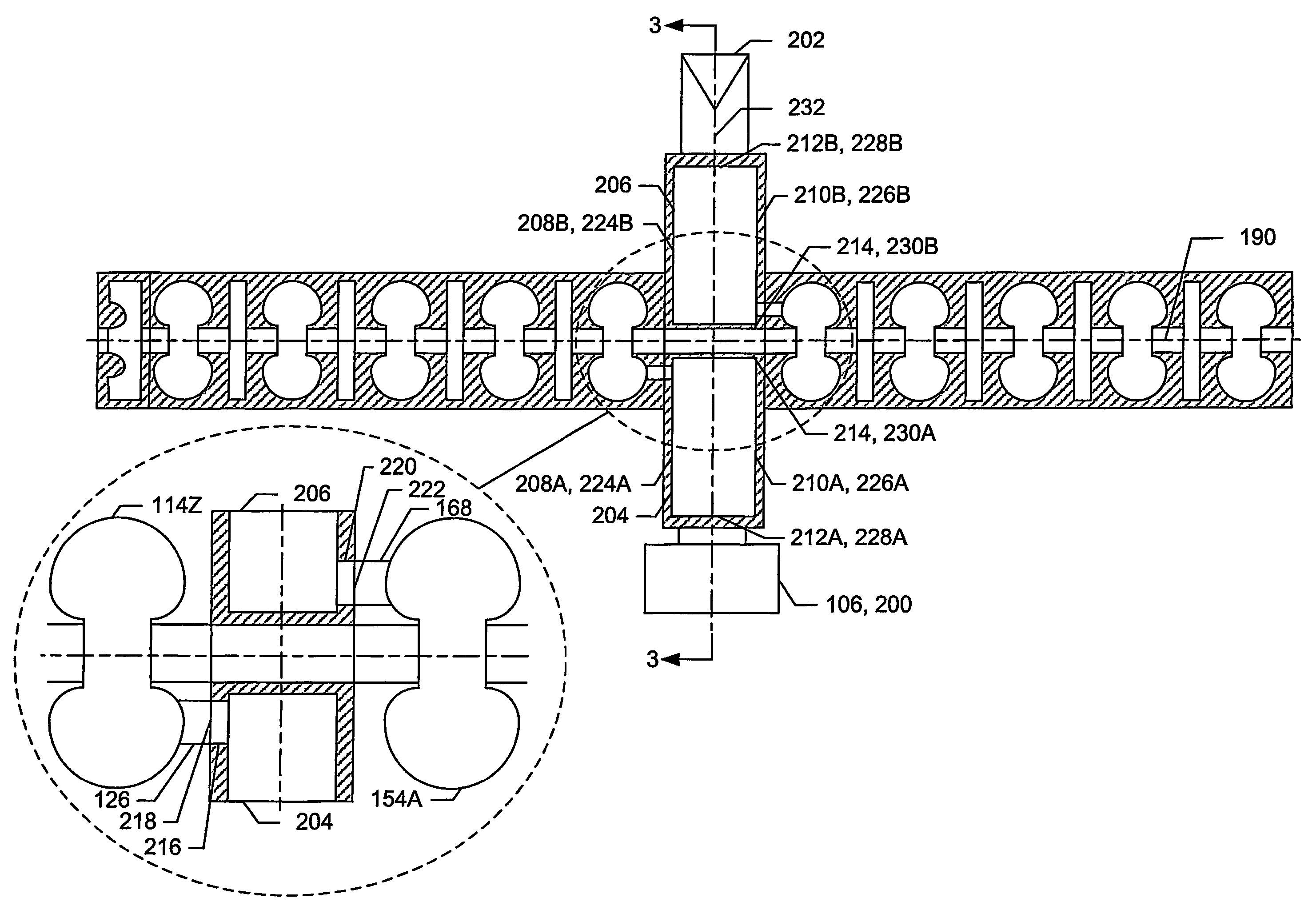
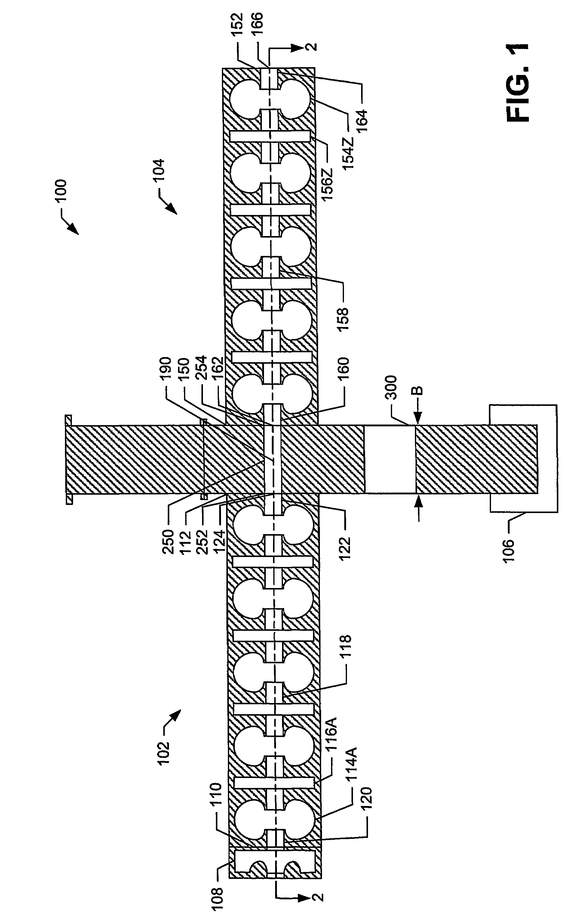
[0021]Referring now to the drawings in which like numerals represent like elements or steps throughout the several views, FIG. 1 displays a schematic sectional view of a particle accelerator system 100 in accordance with an exemplary embodiment of the present invention. The particle accelerator system 100 comprises a first accelerating section 102, a second accelerating section 104, an electromagnetic drive subsystem 106, and an injector 108. Preferably, the first and second accelerating sections 102, 104 comprise standing-wave accelerating sections 102, 104 having a biperiodic accelerating structure which are operable to accelerate charged particles through the transfer of energy from electromagnetic power provided by the electromagnetic drive subsystem 106.

[0022]The first accelerating section 102 has a first end 110 and a second end 112, and includes a plurality of accelerating cavities 114 and a plurality of coupling cavities 116 arranged in an axial arrangement. A coupling cavit...


PUM


Abstract

A particle accelerator system, including apparatuses and methods, that is configurable through repositioning of shorting devices therein to operate at different charged particle beam currents while maintaining optimum transfer of electromagnetic power from electromagnetic waves to one or more accelerating sections thereof, and reducing or eliminating reflections of electromagnetic waves. The particle accelerator system includes at least two accelerating sections and an electromagnetic drive subsystem with portions of the electromagnetic drive subsystem being interposed physically between the accelerating sections, thereby making the particle accelerator system compact. The electromagnetic drive subsystem includes, among other components, a 3 dB waveguide hybrid junction having a coupling window in a narrow wall thereof which is shared by the junction's rectangular-shaped waveguides. By virtue of the coupling window being positioned in a narrow wall rather than a wide wall, the maximal power of the 3 dB waveguide hybrid junction is increased significantly.

Description

CROSS REFERENCE TO RELATED APPLICATION[0001]This application is a national phase application under 35 U.S.C. §371 of international patent application number PCT / US03 / 030646 entitled “Multi-Section Particle Accelerator with Controlled Beam Current” filed on Sep. 29, 2003, now expired, and claims the benefit of priority to U.S. provisional patent application Ser. No. 60 / 414,300 entitled “Two Section Particle Accelerator with Controlled Beam Current” filed on Sep. 27, 2002, now expired.FIELD OF THE INVENTION[0002]The present invention relates, generally, to the field of particle accelerators and, more specifically, to particle accelerators having controlled beam current.BACKGROUND OF THE INVENTION[0003]Standing wave linear accelerators with controlled beam current are utilized in a wide variety of medical and industrial applications, including, radiography, radiotherapy, medical instrument sterilization, food irradiation, and dangerous substance neutralization. In such applications, av...

Claims


Application Information

Patent Timeline
Patent Type & Authority Patents(United States)
IPC IPC(8): H01J23/00H05H7/00H05H7/18H05H7/22H05H9/00
CPCH05H7/00H05H7/18H05H7/22H05H9/00
Inventor ZAVADTSEV, ALEXANDRE A.BOWSER, GARY F.
Owner SCANTECHIBS IP HLDG
Why Eureka
Try Eureka