Method of making an anti-reflection coating

a technology of anti-reflection coating and optical anti-reflection coating, which is applied in the direction of solar heat radiation prevention, solar ray transmission and other directions, can solve the problems of destructive interference between the reflected portion and the interface between air, the reliability of the information transmitted, and the difficulty of image identification, etc., to reduce or eliminate the reflection of electromagnetic radiation of different types

Inactive Publication Date: 2001-01-23
FRAUNHOFER GESELLSCHAFT ZUR FOERDERUNG DER ANGEWANDTEN FORSCHUNG EV
View PDF4 Cites 70 Cited by
  • Summary
  • Abstract
  • Description
  • Claims
  • Application Information

AI Technical Summary

Benefits of technology

Still another object of the invention resides in a method of making an antireflection coating for reducing or eliminating reflections of electromagnetic radiation of different wavelengths.

Problems solved by technology

While the quality of their images has been improved, the images are often difficult to distinguish because of reflections.
Furthermore, the reliability of the information transmitted, for instance, from instrument panels, watch crystals or automotive windscreens is often reduced significantly because of reflections.
If a coating of a thickness .lambda. / 4 is applied to glass (n=1.5), for instance, destructive interference will result between the reflected portion at the interfaces between air and coating as well as coating and glass.
For glass of optimum anti-reflection properties it has to be 1.22 in order to result in close to zero at a wavelength of .lambda.. Such a low index of refraction cannot, however, be achieved with dense coatings.
Such coatings are, however, unsuited for solar applications because the spectrum of solar radiation covers a much wider range.
Such processes do, however, entail problems as they involve the application of at least two coatings.
This results in lower productivity and higher production costs.
While the layers thus produced are relatively abrasion resistant, their high costs of about $60.00 (DM 100.00) to about $100.00 (DM 150.00) per square meter of treated surface area constitute a disadvantage.
On the other hand, sputtered multi-layered interference coatings are suitable only for visual anti-reflection coatings and cannot be applied to every kind of substrate geometry, such as the internal surfaces of tubes, for instance.
But at a cost of about $100.00 (DM 140.00) to about $150.00 (DM 200.00) it is a relatively expensive process.
While the processes for producing these layers are conventional, involving sputtering, vapor deposition or other common coating processes, they are, nevertheless, expensive.
Moreover, another disadvantage of such an anti-reflection coating and of its manufacturing process resides in the fact that because of the light absorber it is very unlikely that the transmission is significantly increased.
The disadvantage of this process is the dispersion occurring as a result of relatively large particles in the coating.
The dispersion results in reduced transmission thus rendering it unsuited for solar applications.
Also, the multiple coating application is very expensive.
These structures tend to be very unstable mechanically.
The disadvantage of this kind of coating, moreover, resides in its complex manufacturing process which, because of the numerous process steps, is very expensive.

Method used


Image

  • Method of making an anti-reflection coating
  • Method of making an anti-reflection coating

Examples


example

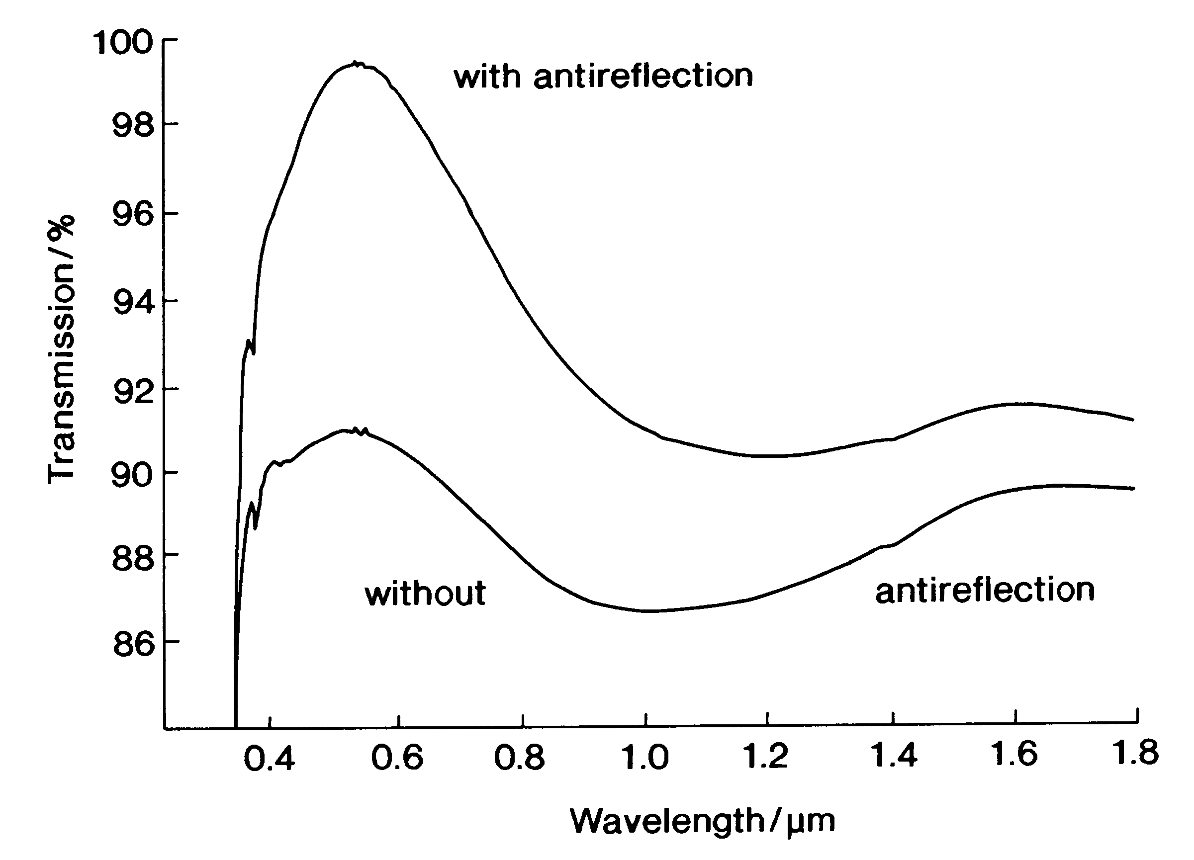
In the presence of 27.0 g of methanol, 7.6 g of polyethylene glycol of a median molecular mass of 10,000 are dissolved in 9.5 g of ammoniacal water having a pH-value of 9,5. The resultant mixture is added to a mixture of 15.2 g of tetramethoxysilane and 80.0 of methanol. After stirring for 10 minutes, the resultant mixture is filtered. After it had aged for about 80 minutes, glass panes were coated by submersion in the mixture. To obtain a particularly uniform coating of about 100 nm the pane to be coated is fixed in the coating bath and the coating solution therein is removed free of vibration within 2 minutes. Following their coating, the panes are dried at 130.degree. C. for 30 minutes. Thereafter, their temperature is raised to 500.degree. C. at a rate of 120 K / h, and the panes are maintained at this temperature for one hour. The result is glass panes with an antireflection coating of a mauve-bluish hue. The resultant antireflection coating was found to have an index of refracti...


PUM

PropertyMeasurementUnit
molar ratioaaaaaaaaaa

Abstract

A method of and a solution for making a highly porous optical antireflection coating of a selectively designed index of refraction, by applying a colloidal dispersion derived from hydrolytically condensing, in the presence of water and a catalyst, one or more silicon compounds of the general formula RaSiX4-a, or precondensates derived therefrom, to a substrate. In the formula, R is an organic group having from 1 to 10 carbon atoms which may be interrupted by oxygen atoms and/or sulfur atoms and/or amino groups, X is hydrogen, halogen, hydroxy, alkoxy, acyloxy, alkylcarbonyl, alkoxycarbonyl or NR'2, R' being hydrogen, alkyl or aryl and a being 0, 1 or 2. The solution also contains colloidally dispersed organic polymers at a molar ratio, relative to the silane, between 0.1 mmol/mol silane and 100 mmol/mol silane, the median molecular mass of the polymer being between 200 and 500,000. Sol-vents, preferably alcohol, may also be present in the solution. After being applied to an optical substrate, the solution is dried and organic components are removed from it to leave a porous coating of predetermined index of refraction.

Description

1. Field of the InventionThe present invention, in general, relates to a composition for, and a method of, making a highly porous anti-flection coating, and, more particularly, to an optical anti-reflection coating for simultaneously improving the transmission and preventing or minimizing undesired reflections of visible and other electromagnetic radiation of the kind occurring, for instance, at cathode ray tubes, liquid crystal displays, instrument panels, spectacle lenses, picture tubes, solar collectors and automotive windscreens.2. The State of the ArtWhen light is penetrating the interface between two media of different diffractive indices a portion of the radiation is reflected. The reflected portion of light vertically impinging upon a pane of glass having an index of refraction n=1.5 is about 4%. If, however, the light falls on the interface at an acute angle, a much greater portion is reflected.Display devices such as, for example, cathode ray tubes or liquid crystal displa...

Claims


Application Information

Patent Timeline
Patent Type & Authority Patents(United States)
IPC IPC(8): C03C17/00C03C17/25F24J2/46F24J2/00G02B1/11G02B1/10G02B1/113
CPCC03C17/007C03C17/009C03C17/25F24J2/4652G02B1/113C03C2217/213C03C2217/425C03C2218/113Y02E10/40F24S80/52F24S80/56F24S70/30
Inventor GLAUBITT, WALTHERGOMBERT, ANDREAS
Owner FRAUNHOFER GESELLSCHAFT ZUR FOERDERUNG DER ANGEWANDTEN FORSCHUNG EV
Why Eureka
Try Eureka