Common axis three mirror anastigmatic optic

a three-mirror anastigmatic and optic technology, applied in the field of three-mirror anastigmatic optics, can solve the problems of special alignment techniques and expensive imaging equipmen

Inactive Publication Date: 2007-04-24
LOCKHEED MARTIN CORP
View PDF16 Cites 29 Cited by
  • Summary
  • Abstract
  • Description
  • Claims
  • Application Information

AI Technical Summary

Problems solved by technology

The alignment and fabrication of TMA's typically require special alignment fixturing, multiple axes and six degrees of freedom for all three mirrors, special alignment techniques and expensive imaging equipment.

Method used


Image

  • Common axis three mirror anastigmatic optic
  • Common axis three mirror anastigmatic optic
  • Common axis three mirror anastigmatic optic

Examples


Embodiment Construction

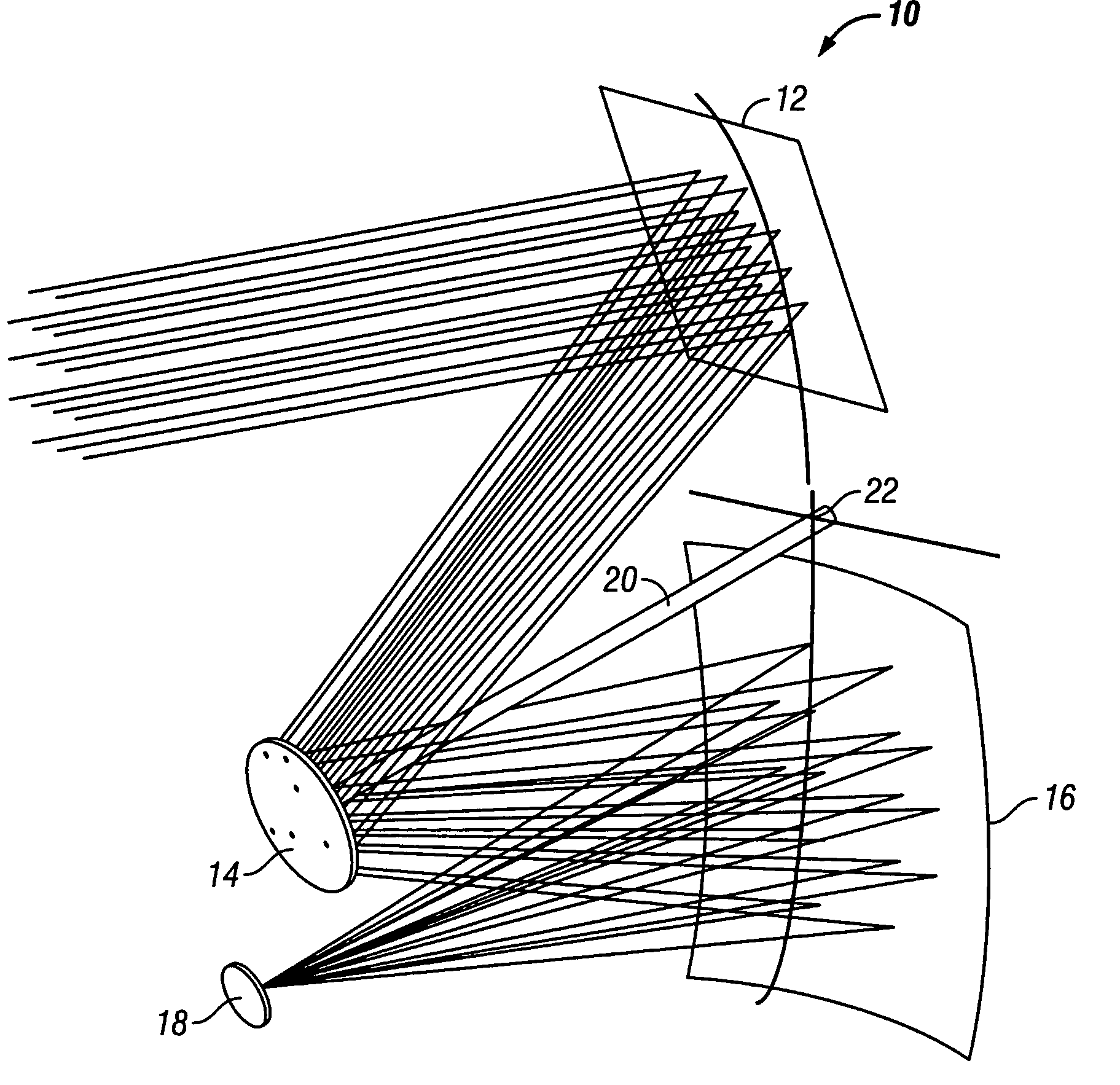
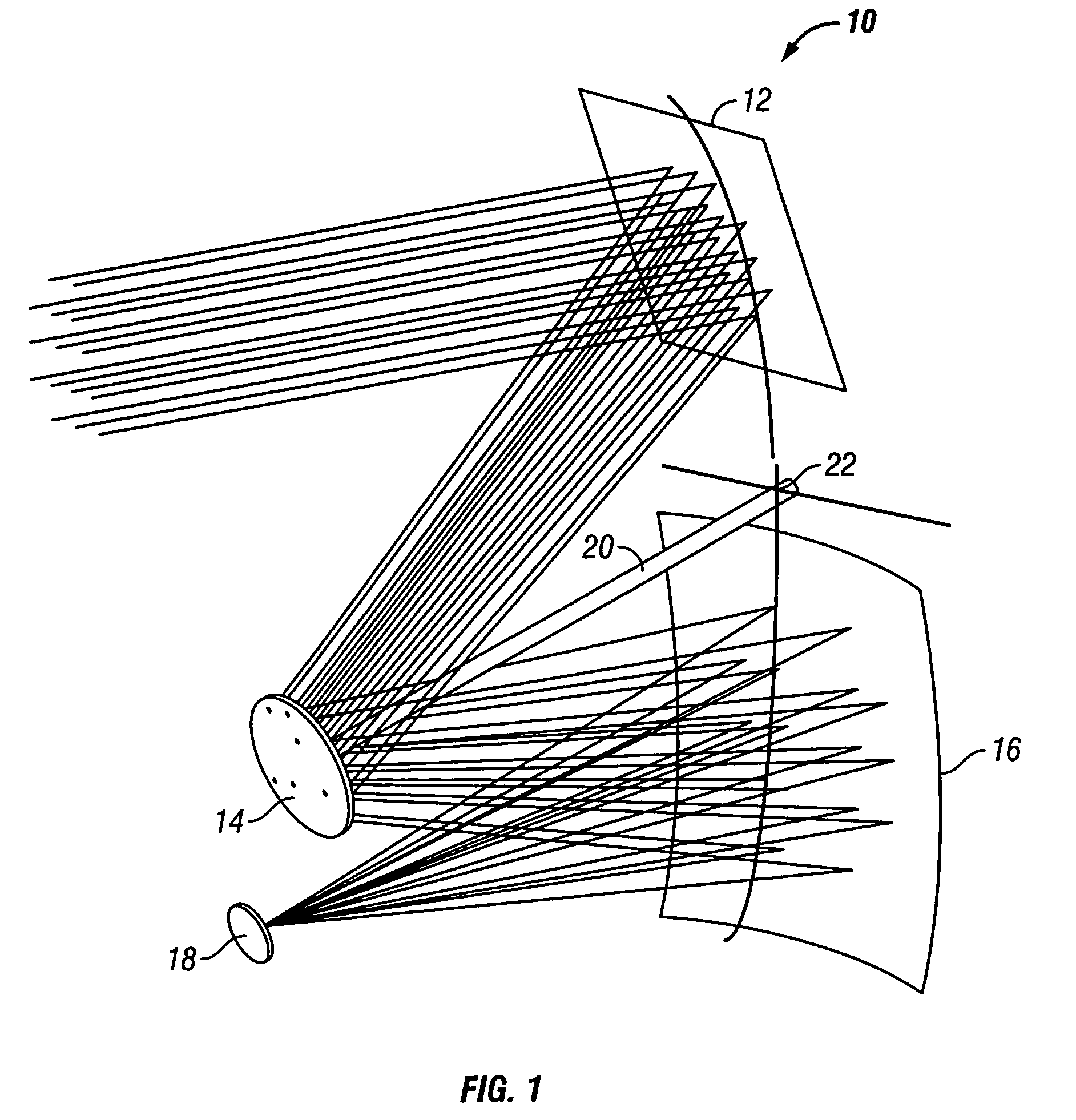
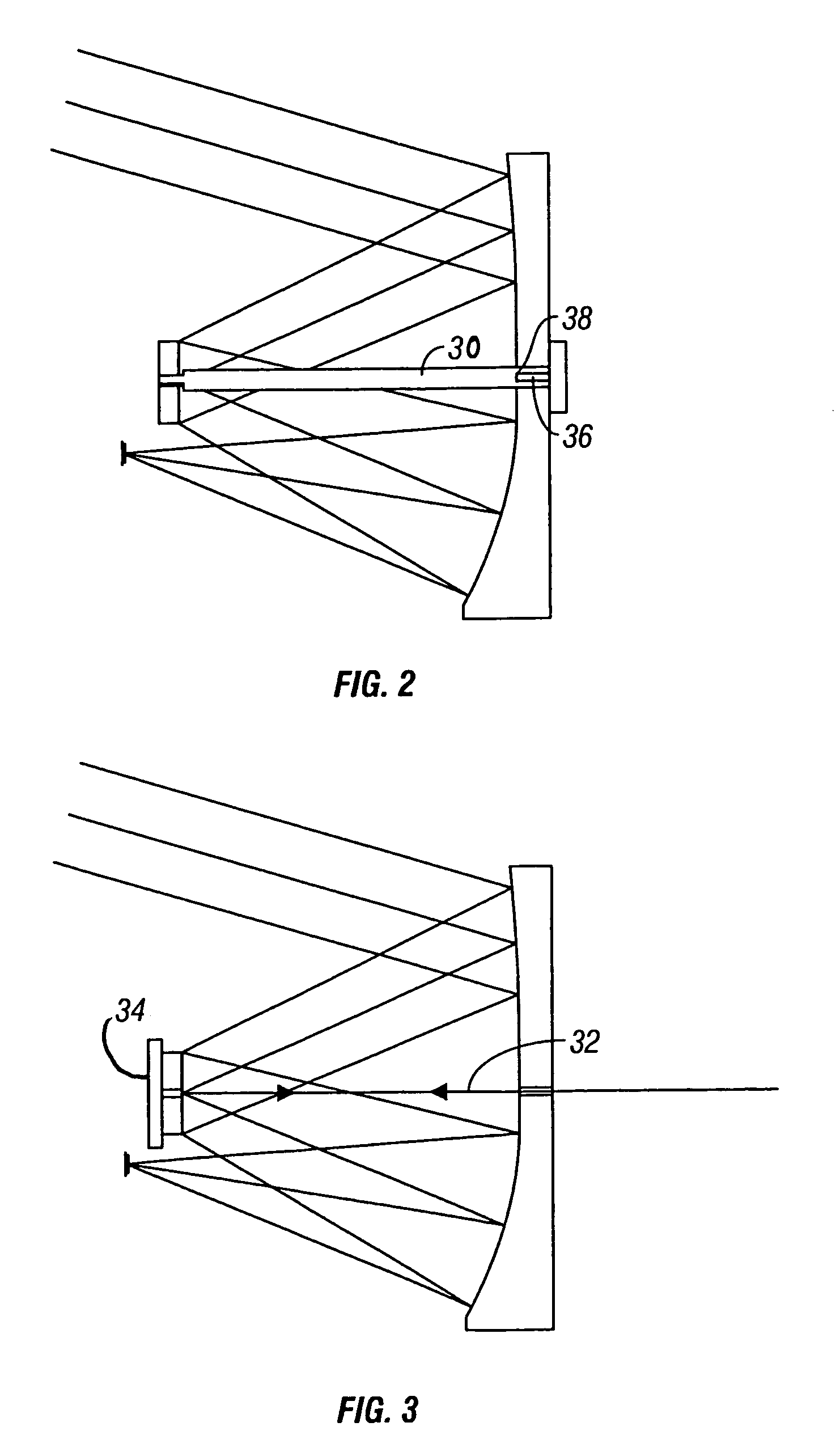
[0017]The common axis Three Mirror Anastigmatic (“TMA”) optical apparatus and method of the invention employs primary and tertiary mirrors at a common vertex with tilt coincident to the alignment axis. The stop of the TMA of the invention is at the secondary mirror, which permits the system to be focused with motion only being performed by the secondary mirror and with only a slight positioning alignment for pixel registration being performed at the image plane.

[0018]The primary and tertiary mirrors having a common vertex permits the diamond turning of the mirror with a common fixture. The mirrors are preferably diamond turned separately referenced to a flat tooling fixture, and then are cut as two halves. They are pinned together into a single assembly, permitting both to be self aligned. The vertex of both mirrors serves as an alignment datum for the secondary mirror to be aligned to the primary-tertiary mirror assembly.

[0019]The present invention employs a wide-field (up to at le...


PUM


Abstract

A three mirror anastigmatic optic (and corresponding method of making) comprising a primary mirror, a secondary mirror, a tertiary mirror, and a vertex common to the primary and tertiary mirrors.

Description

CROSS-REFERENCE TO RELATED APPLICATIONS[0001]Not Applicable.STATEMENT REGARDING FEDERALLY SPONSORED RESEARCH OR DEVELOPMENT[0002]Not Applicable.INCORPORATION BY REFERENCE OF MATERIAL SUBMITTED ON A COMPACT DISC[0003]Not Applicable.COPYRIGHTED MATERIAL[0004]Not Applicable.BACKGROUND OF THE INVENTION[0005]1. Field of the Invention (Technical Field):[0006]The present invention relates to Three Mirror Anastigmatic (“TMA”) optics such as employed in TMA telescopes.[0007]2. Description of Related Art[0008]Three Mirror Anastigmatic (“TMA”) optics employed with sensor technologies typically require complex alignment techniques, requiring Modulation Transfer Function (“MTF”) analyzers, expensive alignment fixtures, and long hours of labor for the system to be aligned. FIG. 4 illustrates a typical prior art TMA optic 2, comprising discrete primary, secondary, and tertiary mirrors 4,6,8, with primary and tertiary mirrors not sharing a common vertex. The alignment and fabrication of TMA's typic...

Claims


Application Information

Patent Timeline
Patent Type & Authority Patents(United States)
IPC IPC(8): G02B17/00G02B23/00
CPCG02B17/0636
Inventor VANSTONE, GARY C.CARTER, III, JAMES A.LEBLANC, RICHARD A.STOPPENBACH, DANIEL J.
Owner LOCKHEED MARTIN CORP
Why Eureka
Try Eureka