Optical System for Detecting and Displaying Aircraft Position and Environment During Landing and Takeoff

an optical system and aircraft technology, applied in the field of systems, can solve the problems of reducing visibility, difficult to operate aircraft, particularly helicopters, landing and takeoff operations, etc., and achieve the effects of reducing the possibility of lateral drift, and effective display

Inactive Publication Date: 2009-06-04
RD2 LLC
View PDF15 Cites 21 Cited by
  • Summary
  • Abstract
  • Description
  • Claims
  • Application Information

AI Technical Summary

Benefits of technology

[0011]In accordance with another feature of the invention, the velocity of the wind with respect to the ground is measured and displayed to the pilot before takeoff to provide information regarding the direction in which the aircraft is likely to drift immediately after takeoff. This is particularly important for a helicopter and is preferably accomplished by directing light beams such as those used for measuring airspeed to a location just beyond the rotors, as this has been determined to be a location that is less likely to be affected by the prop-wash of the rotors. Measuring the airspeed when the aircraft is stationary on the ground provides a measure of the wind velocity that can be effectively displayed to the pilot.
[0012]In accordance with a still further feature of th

Problems solved by technology

Aircraft landing and takeoff operations are particularly dangerous in adverse weather or under conditions of limited visibility.
Aircraft, particularly helicopters, are very difficult to operate during landing when the pilot is unable to observe adequately the motion of the helicopter with respect to the landing area.
For example, as a helicopter approaches a landing site in a desert, downwash from the rotors typically stirs up the sand, which greatly reduces visibility.
This is very dangerous because the pilot cannot adequately observe the landing area to obtain the necessary visual feedback of the aircraft's speed and position.
A h

Method used


Image

  • Optical System for Detecting and Displaying Aircraft Position and Environment During Landing and Takeoff
  • Optical System for Detecting and Displaying Aircraft Position and Environment During Landing and Takeoff
  • Optical System for Detecting and Displaying Aircraft Position and Environment During Landing and Takeoff

Examples


Embodiment Construction

[0021]Reference will now be made in detail to the preferred embodiments of the present invention, examples of which are illustrated in the accompanying drawings.

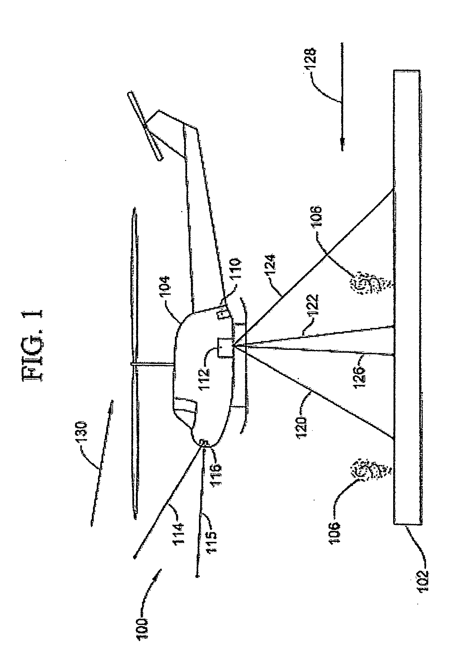
[0022]FIG. 1 depicts an aircraft landing site 100 and an aircraft 104 that is landing or taking off (or hovering), which includes a system for detecting the position and motion of aircraft 104 according to the disclosed embodiments. While the aircraft 104 illustrated in FIG. 1 is a helicopter, the invention is useful with other types of aircraft as well.

[0023]The invention is useful in many different conditions but finds particular utility in those situations where the ground 102 in the landing area comprises easily disturbed sand particles 106 that aircraft 104 stirs up as it lands or takes off, typically because of the downwash from the rotor blades of the helicopter 104. In many environments, such as that of a desert, the sand 106 reduces the visibility by such a degree that the pilot cannot see the ground, which creates ...


PUM


Abstract

A system and method uses light signals to detect and display the position of an airborne vehicle, such as a helicopter, during takeoff or landing or low speed, low altitude operation. A transmitter on the vehicle emits light signals while an optical receiver retrieves reflected light signals. Using light detection and ranging techniques, various parameters, such as altitude, ground speed and relative wind, are calculated based on the Doppler shift within the reflected light signals. The signals are transmitted in three different directions to facilitate the measurements of different Doppler shifts. The parameters are also displayed on a screen or other visual device within the vehicle.

Description

FIELD OF THE INVENTION[0001]The invention relates to systems that determine the position of an aircraft as well as ambient conditions, particularly during takeoff, landing, or low altitude, low speed flight. More particularly, the present invention relates to a system using a laser-based sensor to facilitate safe landing, takeoff, and low altitude, low speed flight, particularly in conditions of limited visibility.BACKGROUND ART[0002]Aircraft landing and takeoff operations are particularly dangerous in adverse weather or under conditions of limited visibility. Aircraft, particularly helicopters, are very difficult to operate during landing when the pilot is unable to observe adequately the motion of the helicopter with respect to the landing area. For example, as a helicopter approaches a landing site in a desert, downwash from the rotors typically stirs up the sand, which greatly reduces visibility. This is very dangerous because the pilot cannot adequately observe the landing area...

Claims


Application Information

Patent Timeline
IPC IPC(8): G01C21/00G01P3/36
CPCG01C5/005G01S13/913G01S17/95G01S17/88G01S17/58G01C23/00Y02A90/10
Inventor ROGERS, PHILIP L.MAMIDIPUDI, PRIYAVADANGATCHELL, PETER A.
Owner RD2 LLC
Why Eureka
Try Eureka