Recording apparatus and recording method

a recording apparatus and recording method technology, applied in the field of recording apparatus and recording method for broadcast program content, can solve the problems of the inability to extend the recording time period by an even recording rate in the same program

Inactive Publication Date: 2007-04-24
KK TOSHIBA
View PDF15 Cites 4 Cited by
  • Summary
  • Abstract
  • Description
  • Claims
  • Application Information

AI Technical Summary

Benefits of technology

[0008]An object of the present invention is to provide a recording apparatus and method capable of automatically recording a part of the recorded program content and a succeeding part of the program content at the same recording rate in a predetermined recording area when broadcast time of the program content is extended during recording the program content, even if the available area of a recording medium becomes insufficient, and capable of the recording program content at an appropriate recording rate by linking with program information.

Problems solved by technology

However, the above prior art apparatus creates available area not by recompressing program contents during recording, but recompressing other recorded program contents.
Thus, if the user refuses recompression of other recorded program contents (to avoid degradation of the picture quality by the recompression), the recording time period cannot be extended.
Further, if the broadcasting time period of a program is extended during recording, it is impossible to extend the recording time period by an even recording rate in the same program.

Method used


Image

  • Recording apparatus and recording method
  • Recording apparatus and recording method
  • Recording apparatus and recording method

Examples


first embodiment

[0035](First Embodiment)

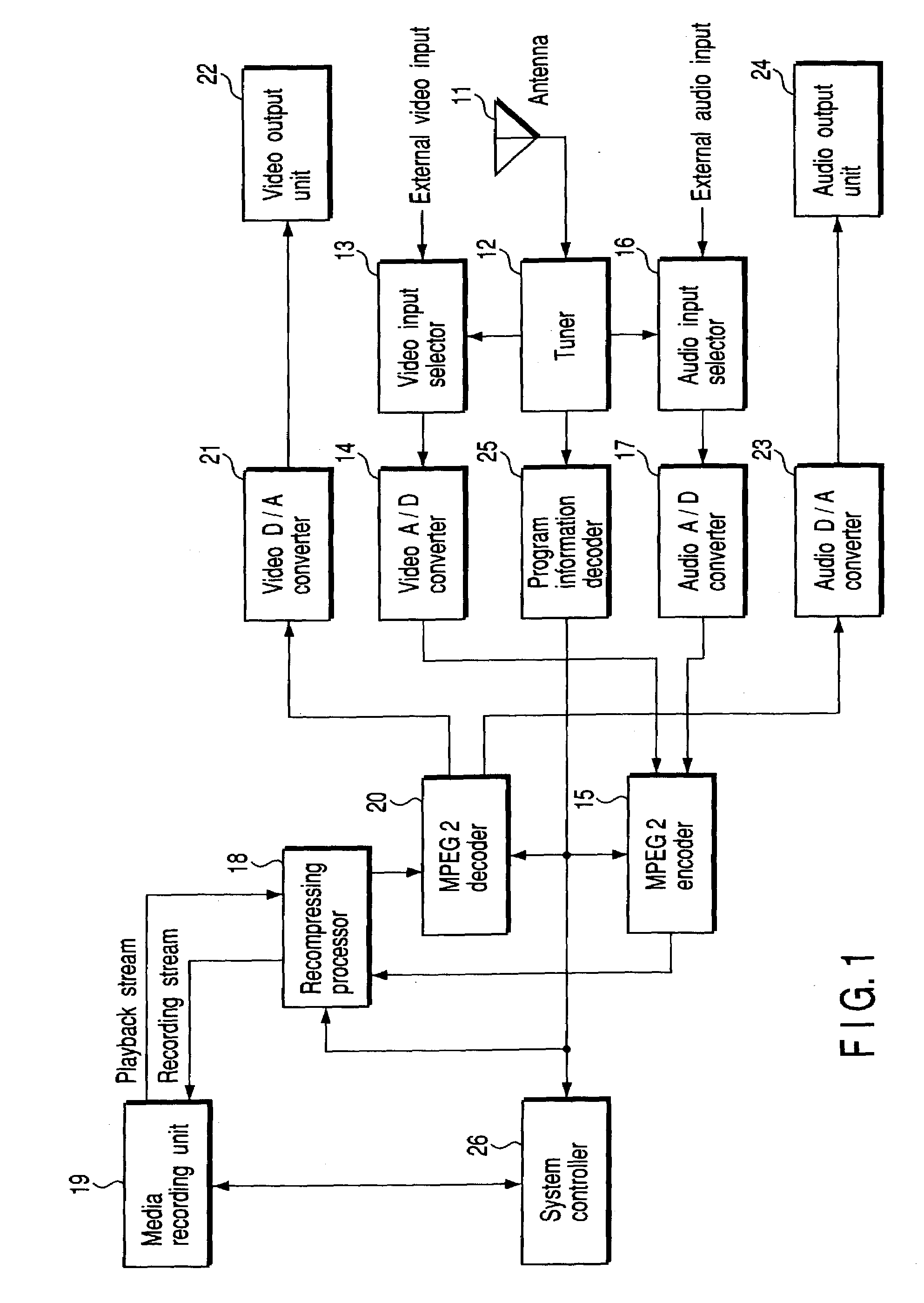
[0036]FIG. 1 is a block diagram showing the construction of a program contents recording / playback apparatus according to a first embodiment of the present invention. In FIG. 1, an antenna 11 receives a broadcast signal. A tuner 12 tune a broadcast signal received by an antenna 11, and program contents comprising a video signal, an audio signal and a data signal are received and detected. The video signal is supplied to a video A / D (Analog / Digital) converter 14 through a video input selector 13, where it is converted into a digital signal of specified format and becomes a video stream. The audio signal is supplied to an audio A / D converter 17 through an audio input selector 16, where it is converted into a digital signal of specified format and becomes an audio stream. The above video stream and audio stream are supplied to MPEG2 (Moving Picture Experts Group Phase 2) encoder 15.

[0037]The above video input selector 13 and audio input selector 16 are used for s...

second embodiment

[0054](Second Embodiment)

[0055]FIG. 4 is a block diagram showing the construction of a program contents recording / playback apparatus utilizing a recording / playback DVD drive unit 27 as a second embodiment. In FIG. 4, the same reference numerals are given to the same components as those in FIG. 1, and only the different components will be explained hereinafter.

[0056]In the playback mode, the recording / playback DVD drive unit 27 shown in FIG. 4 reads a pit string from a DVD recording medium 28 and converts it into an electrical signal by a pickup 271, and amplifies it into a digital signal by a playback amplifier 273. This signal is taken out as a playback stream by a data processor 275, and sent to the recompressing processor 18.

[0057]In the recording mode, the recording stream created by the recompressing processor 18 is converted into the DVD record logic format by a data processor 275, and sent to a recording amplifier 274. This signal is picked up and recorded as a pit string on ...

third embodiment

[0060](Third Embodiment)

[0061]FIG. 5 is a block diagram showing the construction of a program contents recording / playback apparatus applied to digital broadcasting as a third embodiment. In FIG. 5, the same reference numerals are given to the same components as those in FIG. 1, and the construction is partially omitted.

[0062]As shown in FIG. 5, the digital broadcast signal is received by an antenna 31, and tuned by a digital broadcast tuner 32. The tuned digital broadcast signal is demodulated by a digital demodulator 33, thereby a TS (Transport Stream) packet is extracted. The TS packet is applied to a packet separator 34, where it is separated into a video packet, an audio packet and a data packet, and these packets are applied to a video demodulator 35, an audio demodulator 36 and a data demodulator 37, respectively, where they are demodulated and output. As these video and audio outputs are digital signals, they can be applied to the MPEG2 encoder 15 and converted into MPEG sign...


PUM

PropertyMeasurementUnit
speedaaaaaaaaaa
broadcast timeaaaaaaaaaa
timeaaaaaaaaaa

Abstract

A program controller decides extension of a broadcast time of the program content according to program information, calculates the total program time period including the extension time period, calculates an optimum recording rate from the total program time period and the recording capacity, sets the recording rate of new contents in an MPEG2 encoder, and sets the recording rate of rerecorded contents in a recompressing processor. The recompressing processor receives a playback stream from the already recorded contents through a media recording unit, recompresses it and creates a rerecording stream at a lowered recording rate. It also receives the new recording stream from the MPEG2 encoder. It sends these two recording streams alternately to the media-recording unit, thereby recording the rerecording stream and new recording stream alternately.

Description

CROSS-REFERENCE TO RELATED APPLICATIONS[0001]This application is based upon and claims the benefit of priority from the prior Japanese Patent Application No. 2001-401677, filed Dec. 28, 2001, the entire contents of which are incorporated herein by reference.BACKGROUND OF THE INVENTION[0002]1. Field of the Invention[0003]The present invention relates to a recording apparatus and method for recording a broadcast program content on a recording medium such as an optical disk.[0004]2. Description of the Related Art[0005]There is a conventional program contents recording / playback apparatus for recording and playing TV programs, which has a recording time period extending function for unexpected extension of a program. This extending function is such that when the available area of a recording medium runs short, already recorded program contents are once read out, compressed and rerecorded, thereby creating available area to record more program contents. The prior art program contents reco...

Claims


Application Information

Patent Timeline
Patent Type & Authority Patents(United States)
IPC IPC(8): H04N5/91H04N7/26G11B7/0045G11B20/10G11B27/034G11B27/036G11B27/36H04N5/44H04N5/765H04N5/782H04N5/85H04N5/92H04N7/025H04N7/03H04N7/035H04N9/804
CPCG11B27/036G11B27/36H04N5/782H04N9/8042H04N21/4335H04N21/440254H04N21/84G11B27/034G11B2220/2562
Inventor AZUMA, KAZUKI
Owner KK TOSHIBA
Why Eureka
Try Eureka